
a mechanical arm

A robotic arm and manipulator technology, applied in the field of manipulators, can solve the problems of limited application scope of manipulators, complex control process, low positioning accuracy, etc., and achieve the effects of easy storage and disassembly, small mechanical volume, and improved positioning accuracy.

Inactive Publication Date: 2017-03-22
HEILONGJIANG UNIVERSITY OF SCIENCE AND TECHNOLOGY
View PDF7 Cites 0 Cited by
  • Summary
  • Abstract
  • Description
  • Claims
  • Application Information

AI Technical Summary

Problems solved by technology

However, at present, most of the manipulators use the traditional mechanical drive method, which has a cumbersome structure, high mass, complicated control process, and low positioning accuracy, which limits the scope of application of the manipulator to a certain extent.

Method used


Image

  • a mechanical arm
  • a mechanical arm
  • a mechanical arm

Examples


Embodiment Construction

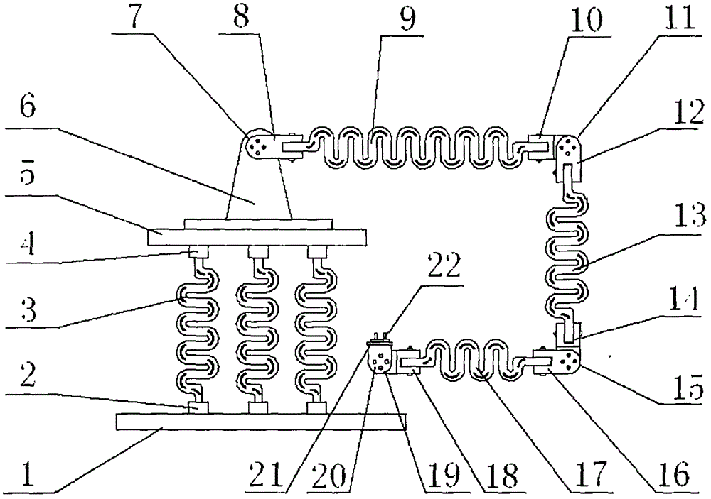
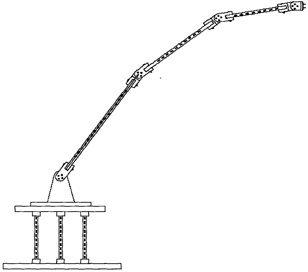
[0013] Embodiments of the present invention will be described in detail below in conjunction with the accompanying drawings. A mechanical arm, six lifting units 3 are arranged between the top of the base 1 and the bottom of the lifting support plate 5, and the upper and lower ends of the six lifting units 3 are respectively connected with the upper fastener 4 and the lower fastener 2. The lifting support plate 5 is fixedly connected to the base 1, the base of the mechanical arm 6 is fixed on the upper end surface of the lifting support plate 5, the first turntable assembly 7 is fixed on the base of the mechanical arm 6, and the first installation head 8 is fixed on the upper end surface of the lifting support plate 5. On a turntable assembly 7, one end of the first telescopic unit 9 is fixedly connected to the first installation head 8, and the second installation head 10 is fixedly installed on the other end of the first telescopic unit 9, and the second turntable assembly 11 ...


PUM


Abstract

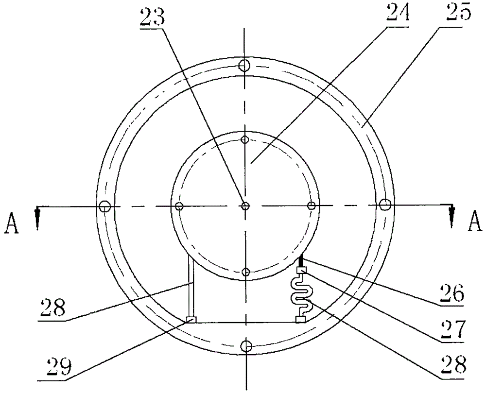
The invention relates to a mechanical arm, and belongs to hoisting carrying machines. A lifting supporting plate is assembled on a base through a lifting unit, a mechanical arm base is fixedly installed on the lifting supporting plate, and a folding or unfolding three-section arm is installed on the mechanical arm base through a rotary disc assembly, an installation head and a stretchable unit which are sequentially connected in series; the rotary disc assembly is formed by a rotating shaft, a rotary wheel, a rotary disc base, a driving belt, a first connecting piece, a second connecting piece and a shape memory polymer driver in an assembled manner; and the lifting unit and the stretchable unit are each formed by shape memory polymer and a shape memory alloy net. According to the mechanical arm, the shape memory characteristic of a shape memory material is creatively used, a traditional mechanical driving mode is replaced with a shape memory effect driving manner, and the mechanical arm has the beneficial effects of being simple in structure, high in positioning accuracy, small in structure weight and flexible and reliable in operation, and reducing the complexity of the operation process.

Description

technical field [0001] The invention belongs to hoisting and transporting mechanical equipment, and mainly relates to a mechanical arm. Background technique [0002] The hoisting and handling machinery can partially or completely replace the operator for production, reduce the labor intensity of the operator, and achieve safe and efficient production. The robotic arm is an important part of the handling machinery, extending the operating range of the manipulator. However, at present, most of the manipulators use the traditional mechanical drive method, which has a cumbersome structure, large mass, complicated control process, and low positioning accuracy, which limits the scope of application of the manipulator to a certain extent. Contents of the invention [0003] The purpose of the present invention is to address the shortcomings of the above-mentioned prior art, and to design and provide a mechanical arm with a new structure, so as to simplify the structure, reduce th...

Claims


Application Information

Patent Timeline
Patent Type & Authority Patents(China)
IPC IPC(8): B25J9/10B25J18/02
Inventor 于月民丁元柱于丽艳乔牧
Owner HEILONGJIANG UNIVERSITY OF SCIENCE AND TECHNOLOGY
Learn More