Optical fiber coloring and curing equipment

A curing equipment and optical fiber technology, which is applied in the field of efficient curing equipment, can solve the problems of uneven light receiving in the gap, affecting the curing quality of the coating, and low energy utilization of the mercury lamp, so as to achieve good curing uniformity and solve the problem of separation , Reduce the effect of curing time

Active Publication Date: 2015-11-25
YANGTZE OPTICAL FIBRE & CABLE CO LTD
View PDF4 Cites 12 Cited by
  • Summary
  • Abstract
  • Description
  • Claims
  • Application Information

AI Technical Summary

Problems solved by technology

Mercury lamps have the disadvantage of requiring considerable power to produce UV radiation of sufficient intensity
For example, curing a single-coated fiber (such as polymer coating) may require a total power consumption of 50kW
Another disadvantage of mercury lamps is that a large amount of energy used to light mercury lamps is emitted as heat instead of ultraviolet rays, which means that mercury lamps have a relatively low energy utilization rate
Among them, the UVLED light source modules are arranged at intervals along the inner cavity of the cylindrical mounting base, and the light source units are arranged in an array along the axial direction. This arrangement will lead to uneven light received in the gaps between the adjacent UVLED light source modules in the circumferential direction, thus affecting the coating. curing quality

Method used


Image

  • Optical fiber coloring and curing equipment
  • Optical fiber coloring and curing equipment
  • Optical fiber coloring and curing equipment

Examples


Embodiment Construction

[0023] The present invention will be further described below in conjunction with accompanying drawing.

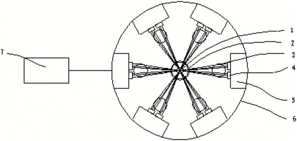
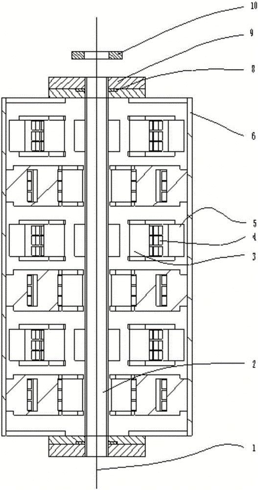
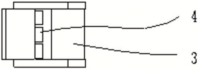
[0024] Such as Figure 1-4 As shown, this embodiment provides a kind of optical fiber coloring and curing equipment, which includes a cylindrical mounting base 6, a UVLED light source module is installed in the inner cavity of the cylindrical mounting base along the circumferential and axial directions, and the The inner cavity is divided into 6 layers of UVLED light source modules along the axial direction, and each layer has 6 UVLED light source modules. The UVLED light source modules installed along the axial direction are arranged at a staggered angle of 20°. The UVLED light source modules include heat dissipation bases 5. The UVLED light source 4 and the cylindrical focusing lens 3, wherein the focusing lens 3 is arranged on the heat dissipation base 5 and is located in front of the UVLED light source 4. The UV light source wavelengths of the UVLED light source 4 are 3...


PUM

PropertyMeasurementUnit
wavelengthaaaaaaaaaa

Abstract

The invention discloses optical fiber coloring and curing equipment which comprises a cylindrical installing base. UVLED light source modules are installed in an inner cavity of the cylindrical installing base in the peripheral direction and the axial direction. Cylindrical surface focusing lenses are arranged in front of the light-emitting faces of the UVLED light source modules, and therefore ultraviolet light rays transmitted by the UVLED light source modules can be focused on a curing axis. The equipment is characterized in that the UVLED light source modules vertically arranged in the axial direction are arranged in a staggered mode in the peripheral direction, and one cylindrical surface focusing lens is correspondingly configured in front of each UVLED light source module. As the UVLED light source modules, arranged in the axial direction, of the adjacent sets are arranged in the staggered mode, light received by the surfaces of optical fibers is more uniform, the equipment has higher curing efficiency and better curing uniformity, curing time is shortened, and working efficiency and coating curing quality of optical fiber drawing are improved.

Description

technical field [0001] The invention relates to a device for efficiently curing the coating layer of a high-speed drawn optical fiber, and belongs to the technical field of optical fiber manufacturing equipment. Background technique [0002] The outside of the optical fiber usually has one or several layers of coating as its protective layer. In a typical optical fiber drawing process, when the preform is melted and drawn into a bare optical fiber, two or more layers of coatings need to be coated on-line. Usually a relatively soft inner coating prevents microscopic bending of the fiber, and a relatively hard outer coating provides additional protection and better handling of the fiber. These organic polymer coatings can be cured onto the fiber surface by heating (thermal curing) or ultraviolet light irradiation (UV curing). Ultraviolet (UV) curing of optical fiber coating refers to the use of ultraviolet rays to trigger rapid polymerization and crosslinking of liquid coati...

Claims


Application Information

Patent Timeline
Patent Type & Authority Applications(China)
IPC IPC(8): C03C25/10C03C25/24
Inventor 高莹余学运卢松涛黄财明万秀强吴杰马军
Owner YANGTZE OPTICAL FIBRE & CABLE CO LTD
Why Eureka
Try Eureka