
Axial piston pump

A technology of axial plunger pump and plunger, which is applied in the direction of pump components, variable displacement pump components, components of pumping devices for elastic fluid, etc. Breakage, structural strength reduction and other problems, to achieve the effect of improving unilateral wear, increasing working pressure, and increasing design space

Active Publication Date: 2017-08-01
HANGZHOU LVJU TECH +1
View PDF1 Cites 1 Cited by
  • Summary
  • Abstract
  • Description
  • Claims
  • Application Information

AI Technical Summary

Problems solved by technology

This technical solution is used to improve the return stroke problem in the prior art through the setting of the stepped plunger and the plunger hole, but the processing of the stepped plunger and the plunger hole needs to ensure the coaxiality, which is difficult, and for The cooperation between the two in the plunger pump requires a higher level of precision, which further increases the difficulty of processing. Secondly, compared with the original plunger, the structural strength of the stepped plunger is reduced, and the plunger pump may cause the plunger when it is running. In the case of plug fracture, the cylinder block still needs to rotate in this technical solution, which brings certain pressure pulsation, hydraulic shock and noise to the hydraulic system, which affects the safe operation of the entire hydraulic system

Method used


Image

  • Axial piston pump
  • Axial piston pump
  • Axial piston pump

Examples


Embodiment Construction

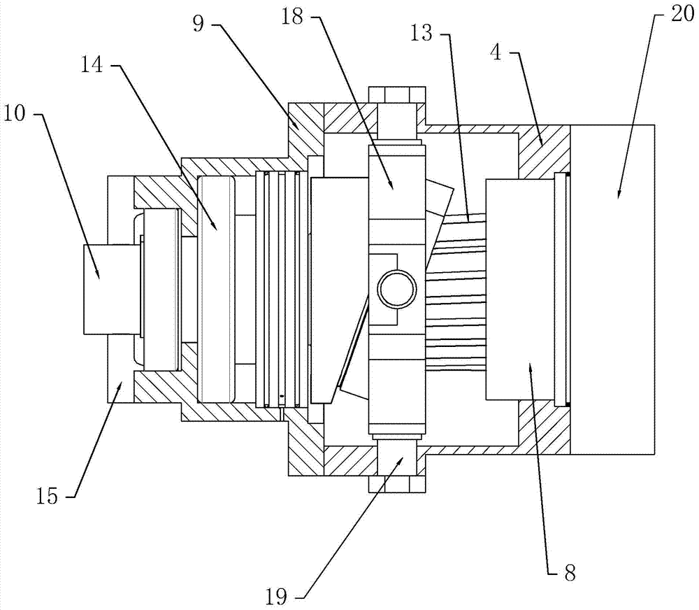
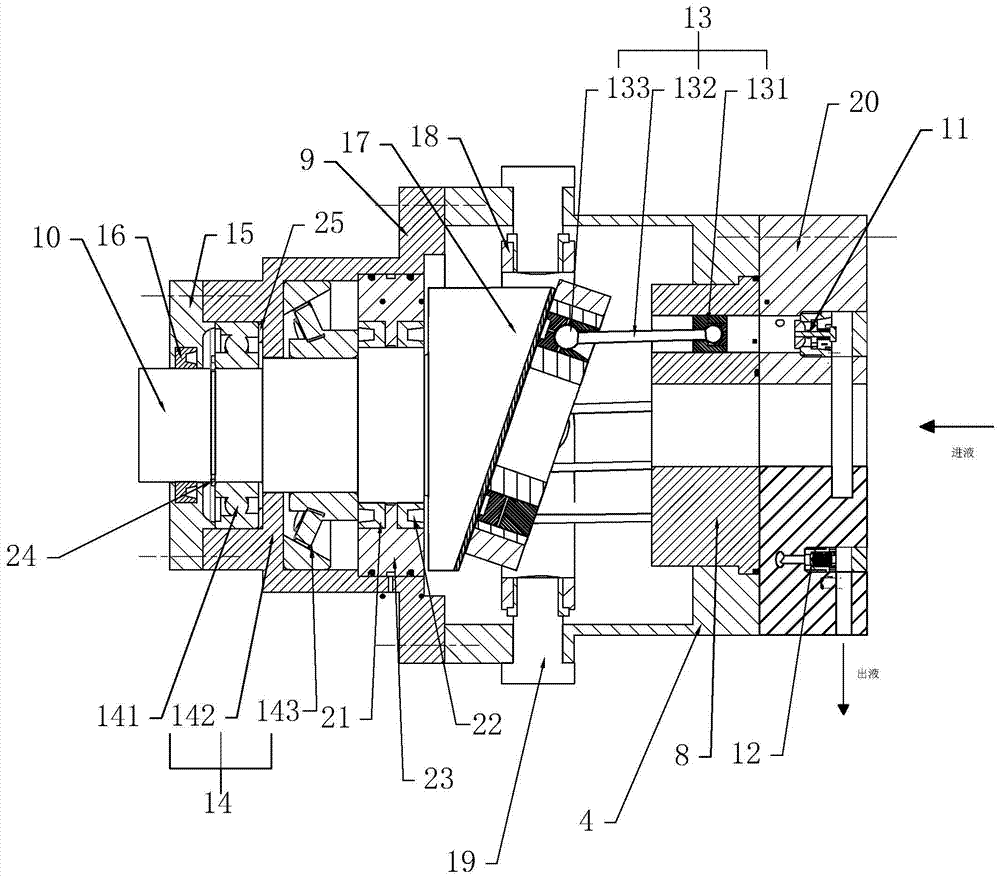
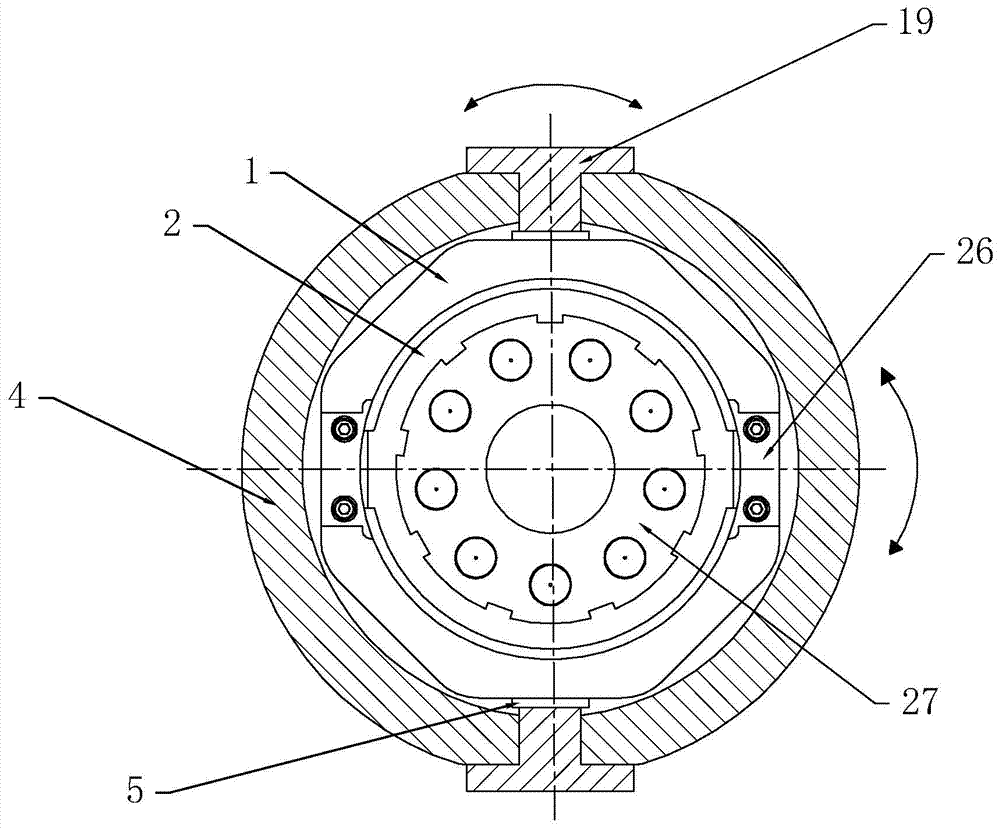
[0030] refer to Figure 1 to Figure 5 The embodiments of the present invention will be further described.

[0031] An axial piston pump, comprising an end cover 15, a front housing, a pump shaft 10 arranged in the front housing 9, a rear housing 4, a swash plate 17 installed in the rear housing 4, and a cylinder body 8, The end cover 15, the front casing 9, the rear casing 4 and the cylinder body 8 are fixedly connected in sequence, and the end of the pump shaft 10 facing away from the casing is connected to the swash plate 17, and the swash plate and the remains of the pump shaft are integrally arranged. The rear housing 4 is also provided with a cross wobble plate 18 and a plunger assembly 13, and the cylinder body 8 is provided with a plunger hole, a valve hole, a pressing out valve group 12 and a pressing in valve group, and the pressing out valve group 12 and The press-in valve group is located in the valve hole, one end of the plunger assembly 13 is embedded in the plunge...


PUM


Abstract

The invention discloses a novel axial plunger pump, the main points of which are technical solutions including an end cover, a front casing, a pump shaft arranged in the front casing, a rear casing, a swash plate installed in the rear casing, and a cylinder body , the end cover, the front casing, the rear casing and the cylinder body are fixedly connected in sequence, the end of the pump shaft facing away from the casing is connected to the swash plate, and the plunger pump is also equipped with a cross wobble plate and a plunger assembly , the cylinder body is provided with a plunger hole, a valve hole, a pressure-out valve group and a pressure-in valve group, the pressure-out valve group and the pressure-in valve group are located in the valve hole, and one end of the plunger assembly is embedded in the plunger hole , the other end of the plunger assembly is connected to the cross wobble plate, the cross wobble plate is in conflict with the swash plate, and the shoe plate integrates the return plate and the shoe in the prior art, and the shoe and the plunger ball head are inlaid into one, reducing the The lateral force of the cylinder body and the plunger seat is reduced, and at the same time, it is beneficial to increase the swing angle of the swash plate, which is beneficial to increase the return distance of the plunger seat, increase the displacement of the plunger pump, and improve the performance of the plunger pump. efficiency, further simplifying the cylinder design.

Description

technical field [0001] The present invention relates to the field of hydraulic pumps, more specifically, it relates to an axial piston pump. Background technique [0002] The pump is the power component and core component of the pressure system, so its design and research are of great significance. The structural forms of the pump mainly include plunger type, vane type, and gear type. The sealing effect of the vane type and gear type pumps is poor, the volumetric efficiency is low, and the leakage is serious when the working pressure is increased. The three pairs of key friction pairs in the commonly used plunger pump structure include the plunger and the cylinder bore, the sliding shoe and the swash plate, the flow plate and the end face of the cylinder body, all of which are in surface contact, so the sealing effect is relatively good. Under the working conditions of the medium, it can ensure a relatively high volumetric efficiency, and compared with the vane and gear pum...

Claims


Application Information

Patent Timeline
Patent Type & Authority Patents(China)
IPC IPC(8): F04B53/00F04B53/14F04B53/10
Inventor 岳艺明徐兵李莹黎贻晨
Owner HANGZHOU LVJU TECH
Learn More