High-speed directly connected water vapor compressor
A water vapor and compressor technology, applied in the field of high-speed direct-connected water vapor compressors, can solve the problems of reducing the overall efficiency of ordinary high-speed centrifugal compressors, damage to electrical insulation of bearing lubricating oil, unreliable torque transmission, etc., and achieve simple assembly, Ease of maintenance and simplification of installation operations
- Summary
- Abstract
- Description
- Claims
- Application Information
AI Technical Summary
Problems solved by technology
Method used
Image

Examples
Embodiment Construction
[0024] The present invention will be further elaborated below in conjunction with accompanying drawing and embodiment, direction of the present invention is with figure 1 prevail.
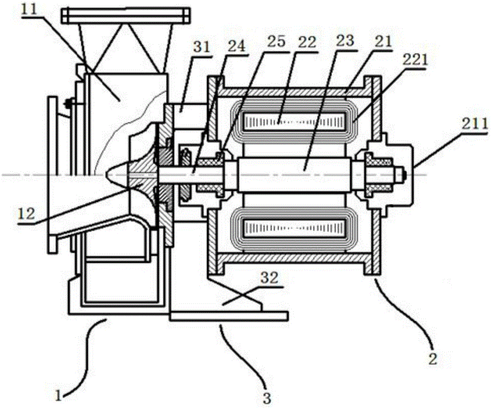
[0025] Such as Figure 1 to Figure 2 As shown, a high-speed direct-connected water vapor compressor includes a water vapor centrifugal compressor 1, a connection base 3 and a high-speed motor 2, and the water vapor centrifugal compressor 1 and the high-speed motor 2 are connected into one body through a semi-open connection base 3 .
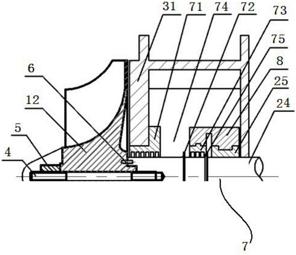
[0026] The water vapor centrifugal compressor 1 includes a volute 11 and an impeller 12 installed in the volute 11, the volute 11 is provided with a volute installation panel and is provided with an inlet and outlet connected to the steam pipeline of the MVR evaporator, and the impeller 12 is installed On the inner side of the volute installation panel, the impeller 12 adopts a three-way semi-open impeller, which is programmed and processed by a five-axis CNC machin...
PUM
 Abstract
Description
Claims
Application Information
 - Generate Ideas
- Intellectual Property
- Life Sciences
- Materials
- Tech Scout
- Unparalleled Data Quality
- Higher Quality Content
- 60% Fewer Hallucinations
Browse by: Latest US Patents, China's latest patents, Technical Efficacy Thesaurus, Application Domain, Technology Topic, Popular Technical Reports.
© 2025 PatSnap. All rights reserved.Legal|Privacy policy|Modern Slavery Act Transparency Statement|Sitemap|About US| Contact US: help@patsnap.com