Supercharge Your Innovation With Domain-Expert AI Agents!

Laser diode area array pumped uniformity detection apparatus

A laser diode and detection device technology, applied in the laser field, can solve the problems of low accuracy of detection results, achieve high accuracy and ensure accuracy

Inactive Publication Date: 2015-11-25
ACAD OF OPTO ELECTRONICS CHINESE ACAD OF SCI
View PDF7 Cites 0 Cited by
  • Summary
  • Abstract
  • Description
  • Claims
  • Application Information

AI Technical Summary

Problems solved by technology

[0004] In the existing technology, the detection of the uniformity of the pump light is mostly qualitative observation, such as the detection of the fluorescence distribution on the light-receiving surface and the observation of the spot; or the use of software for ray tracing simulation, these detection methods are inevitable There is a problem of low accuracy of detection results

Method used


Image

  • Laser diode area array pumped uniformity detection apparatus
  • Laser diode area array pumped uniformity detection apparatus

Examples


Embodiment 1

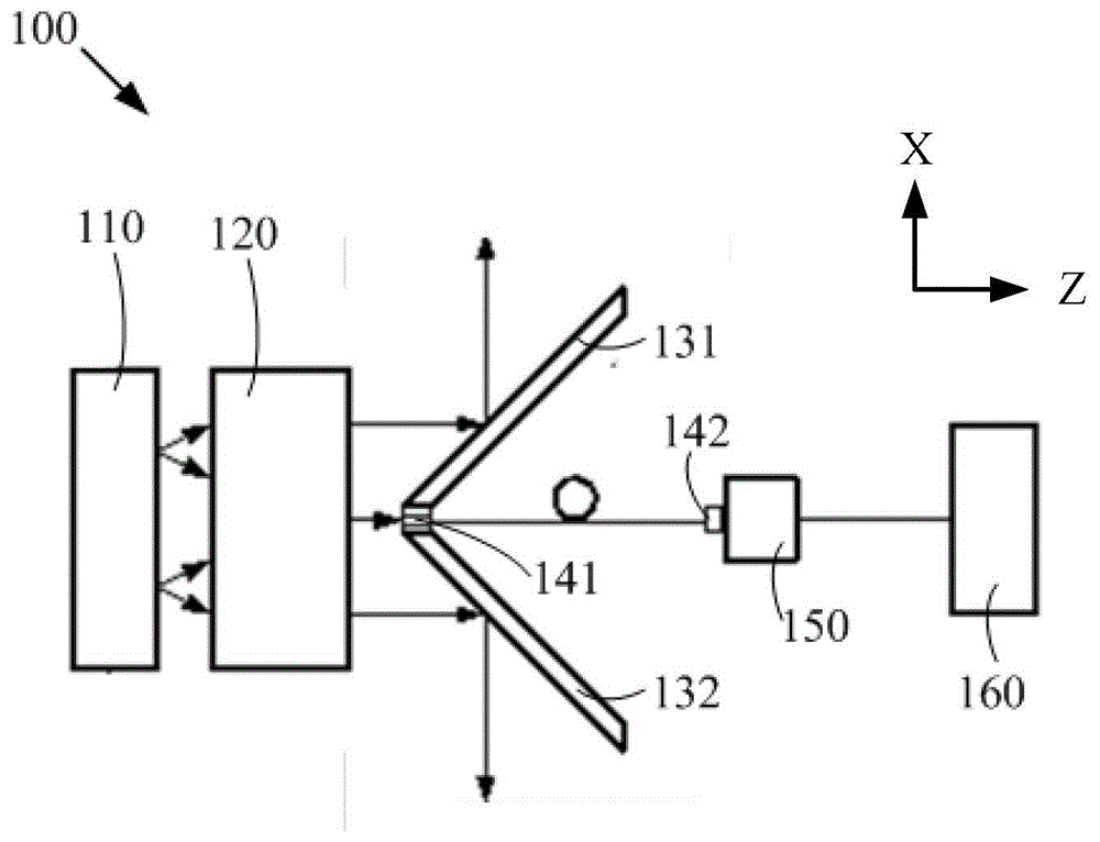
[0020] see figure 1 , figure 1 It is a structural schematic diagram of an embodiment of a laser diode area array pumping uniformity detection device in an embodiment of the present invention. Such as figure 1 As shown, the laser diode array pump light uniformity detection device 100 includes a laser diode array 110, an optical waveguide 120, a V-shaped reflector (including reflector 131 and reflector 132), a laser transmission fiber (including optical fiber connector 141 and fiber end 142), a driver (not shown), a power meter probe 150 and a processor 160.

[0021] Such as figure 1 As shown, the horizontal direction of the paper is the z direction, the vertical direction of the paper is the x direction, and the direction perpendicular to the paper is the y direction. Specifically, the LD (Laser Diode, laser diode) array can be formed by stacking several LD ​​arrays along the x direction, the fast axis direction of the laser diode array is the y direction, and the slow axis...

Embodiment 2

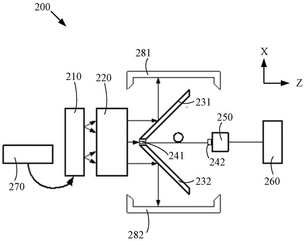
[0035] see figure 2 , figure 2 It is a structural schematic diagram of another embodiment of a laser diode area array pumping uniformity detection device in the embodiment of the present invention. Such as figure 2 As shown, a laser diode array pump uniformity detection device 200 includes a laser diode array 210, an optical waveguide 220, a V-shaped reflector (including reflector 231 and reflector 232), laser transmission optical fiber (including optical fiber connector 241 and fiber end 242), a driver (not shown), a power meter probe 250 and a processor 260.

[0036] The differences between this embodiment and Embodiment 1 include:

[0037] 1. A laser diode array pumping uniformity detection device 200 also includes a water cooler 210 for cooling the laser diode array 210, especially suitable for high-power laser diode arrays.

[0038] 2. A laser diode area array pumping uniformity detection device 200 further comprising two light receiving plates 281 and 282 respecti...


PUM


Abstract

The embodiment of the invention discloses a laser diode area array pumped uniformity detection apparatus. The apparatus comprises a laser diode area array; an optical waveguide for performing uniformization on pumped light emitted by the laser diode area array; a V-shaped reflector panel for reflecting the pumped light emitted by the optical waveguide towards the two sides of the optical waveguide; a laser transmission fiber including a fiber joint and a fiber tail end, wherein the fiber joint is fixed on the V-shaped reflector plate for receiving the pumped light emitted by the optical waveguide; a driver for driving the V-shaped reflector panel to move relative to the light-emitting surface of the optical waveguide according to a predetermined mode; a power meter probe disposed at the backlight side of the V-shaped reflector plate for detecting the optical power value of light emitted by the fiber tail end; and a processor for receiving the optical power value and analyzing the optical power value according to the predetermined mode so as to obtain uniformity distribution. According to the embodiment of the invention, quantification processing can be performed on the uniformity distribution of a certain light receiving area, and the laser diode area array pumped uniformity detection apparatus has the advantage of quite high detection accuracy.

Description

technical field [0001] The invention relates to the field of laser technology, in particular to a laser diode area pump uniformity detection device. Background technique [0002] Solid-state lasers pumped by semiconductors have been widely used due to their advantages such as small thermal effect, good stability, and compact structure. In the 1980s, with the development of semiconductor laser technology, the performance of a single laser diode has been greatly improved, especially the rapid development of semiconductor arrays, making solid-state lasers full of vitality. [0003] Whether it is for the traditional rod-shaped laser working medium or the slab-shaped laser working medium, in order to obtain high-power and high-beam-quality laser output, a high-power and high-performance pump source becomes an ideal pumping source. structure, and the semiconductor array just meets our needs. Not only that, in order to obtain laser output with high beam quality, we not only need ...

Claims


Application Information

Patent Timeline
Patent Type & Authority Applications(China)
IPC IPC(8): G01M11/02
Inventor 樊仲维贾丹陈艳中郭广妍康治军何建国刘昊岳龙貊泽强赵天卓王江
Owner ACAD OF OPTO ELECTRONICS CHINESE ACAD OF SCI
Features
  • R&D
  • Intellectual Property
  • Life Sciences
  • Materials
  • Tech Scout
  • Unparalleled Data Quality
  • Higher Quality Content
  • 60% Fewer Hallucinations
Learn More