Time-domain calibration method for electromagnetic pulse magnetic-field probe

A technology of electromagnetic pulse and calibration method, which is applied in the direction of measuring electrical variables, measuring devices, instruments, etc., can solve the problems of complicated calibration experiment process, long time consumption, limitations, etc., achieve uniformity and good shielding performance, and prevent electromagnetic leakage , the effect of accurate time domain calibration

Active Publication Date: 2015-11-25
中国人民解放军63973部队
View PDF9 Cites 20 Cited by
  • Summary
  • Abstract
  • Description
  • Claims
  • Application Information

AI Technical Summary

Problems solved by technology

One measurement can only calibrate the electric field probe at a single frequency point, and multiple measurements are required to achieve the calibration of the electric field probe to be tested. The calibration experiment process of this method is complicated and takes a long time
[0004] In 2009, the patent CN101561481 disclosed a calibration method for high-frequency electric field probes. This calibration method uses the standard antenna method to realize the frequency domain calibration of the electric field probe. Since this method is calibrated in the frequency domain, the calibration experiment process is complicated, and this method can only Calibrating Small Size Electric Field Probes
[0005] The article "Time Domain Calibration of Optical Fiber Transmission Pulse Electric Field Sensor" published in the 6th issue of "Safety and Electromagnetic Compatibility" (86-88 pages) in 2006 discloses a time domain calibration device and method for electromagnetic pulse electric field sensors. Using the standard field method, the standard electric field generated by the TEM cell realizes the time-domain calibration of the electric field sensor. Due to the limitation of the working space inside the TEM cell, this calibration method can only be used for time-domain calibration of the small-volume electric field probe.

Method used


Image

  • Time-domain calibration method for electromagnetic pulse magnetic-field probe
  • Time-domain calibration method for electromagnetic pulse magnetic-field probe

Examples


Embodiment 1

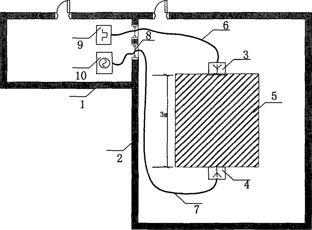
[0031] Such as figure 1 As shown, the time-domain calibration method for the electromagnetic pulse electric field probe provided in this embodiment includes a control room 1, an anechoic chamber 2, a transmitting antenna 3, a standard receiving antenna 4, an area for laying wave-absorbing materials 5, a shielded radio frequency cable 6, a shielded RF signal line 7 , adapter board 8 , pulse signal source 9 , and digital oscilloscope 10 . The transmitting antenna 3 and the standard receiving antenna 4 are placed in the anechoic room 2, and the position marks of the transmitting antenna and the receiving antenna are posted on the ground of the anechoic room 2, and the pulse signal source 9 and the digital oscilloscope 10 are placed in the control room 1 in. The control room 1 is effectively isolated from the anechoic room 2 , and the connection between devices and signal transmission are performed through the adapter board 8 on the wall of the anechoic room 2 . During the calib...

Embodiment 2

[0046] The transmitting antenna line 3 and the standard receiving antenna 4 adopt broadband antennas.

[0047] The object of the present invention is to provide a time-domain calibration method for an electromagnetic pulse electric field probe. The calibration method adopts the standard antenna method, and the entire calibration experiment is carried out in an anechoic chamber. The anechoic chamber provides a relatively "clean" electromagnetic environment for the calibration experiment. The signal source and digital oscilloscope are placed in the control room of the anechoic chamber, and are effectively isolated from the working antenna, reducing the interference caused by electrical equipment during the calibration process. The time-domain calibration method of the electromagnetic pulse electric field probe provided by the invention can quickly and accurately complete the time-domain calibration of the larger-sized electromagnetic pulse electric field probe.


PUM


Abstract

The invention relates to a time-domain calibration method for an electromagnetic pulse magnetic-field probe. The method is used for calibrating an electromagnetic pulse magnetic-field probe in the time domain. The method comprises an anechoic chamber, a pulse signal source, a transmitting antenna, a standard receiving antenna, and a digital oscilloscope. According to the method, the transmitting antenna and the standard receiving antenna are placed at fixed places in the anechoic chamber, and the pulse signal source and the digital oscilloscope are placed in an anechoic chamber control room. A pulse voltage signal is fed into the transmitting antenna via a through-wall cable by the pulse signal source, and the transmitting antenna radiates an electromagnetic pulse to the outside. The standard receiving antenna receives the pulse electric field radiated from the transmitting antenna. The digital oscilloscope is connected with the receiving antenna and a to-be-calibrated magnetic-field probe via another through-wall cable so as to record a voltage signal waveform measured by the receiving antenna and the to-be-calibrated magnetic-field probe. Measured voltage signals are processed based on a certain algorithm, so that the time-domain transfer function of the to-be-calibrated magnetic-field probe is obtained. In this way, the time-domain calibration on the electromagnetic pulse magnetic-field probe can be realized.

Description

technical field [0001] The invention relates to a time-domain calibration method for an electromagnetic pulse electric field probe, which belongs to the field of transient electromagnetic pulse electric field measurement and provides a calibration method for transient electromagnetic pulse electric field measurement equipment. Background technique [0002] Electromagnetic pulse measurement is an important part of electromagnetic pulse test. Electromagnetic pulse measurement needs to obtain the time domain waveform of the electric field or magnetic field to be tested. Therefore, it is necessary to directly calibrate the probe (equipment) for measuring electromagnetic pulse electric field or magnetic field in the time domain. [0003] The commonly used electric field probe calibration method is mainly calibrated in the frequency domain. In this method, the signal source outputs a continuous wave signal with a specific amplitude and specific frequency during the calibration proc...

Claims


Application Information

Patent Timeline
Patent Type & Authority Applications(China)
IPC IPC(8): G01R35/00
Inventor 李欣张雪芹梁睿曹保锋范江兵
Owner 中国人民解放军63973部队
Why Eureka
Try Eureka