Optical image-taking lens

A lens and optical technology, applied in the field of imaging lens sets, can solve the problems of inability to meet image quality requirements, insufficient lens resolution, limited ultra-wide-angle demand, etc. Effect

Active Publication Date: 2015-11-25
彩晶光电科技(昆山)有限公司
View PDF9 Cites 2 Cited by
  • Summary
  • Abstract
  • Description
  • Claims
  • Application Information

AI Technical Summary

Problems solved by technology

[0005] Furthermore, with the rapid development of semiconductor technology, smaller and smaller pixel sizes (pixelsize) are used in portable test imaging systems. As a result, the continuous improvement of sensor (CCD / CMOS) pixels requires the resolution of optical lenses to be As a result, the resolution of the original three-element lens is not enough. In addition, for example, US7,365,920 uses a laminated glass lens to reduce chromatic aberration and increase resolution. Although the design can improve performance, it is not easy to shrink volume
[0006] After the recent improvement of plastic lens manufacturing technology, the 3P structure has been used in miniaturized mobile phone lenses, such as US Patent No. 7,394,602, which consists of an all-plastic three-piece lens. However, the 3P structure still has its limit, which makes it unable to meet the image quality requirements of current photosensitive originals with reduced pixels and enhanced image quality.
[0007] In addition, the mobile phone lens design with 4P structure has also been partially applied in the current market, such as US Patent No. 7,453,654, which uses a patent with a four-piece plastic lens structure, but the FOV angle of a lens with a four-piece structure is generally about 60°~ Around 70°, its demand for ultra-wide-angle is still limited

Method used


Image

  • Optical image-taking lens
  • Optical image-taking lens
  • Optical image-taking lens

Examples


Embodiment Construction

[0030] The embodiments will be described in more detail below with reference to the accompanying drawings; however, these embodiments can be implemented in different forms, and therefore should not be viewed as being limited only to the embodiments presented here. Rather, these embodiments are intended to make this disclosure more thorough and complete, and to fully convey the scope of the invention to those skilled in the relevant arts.

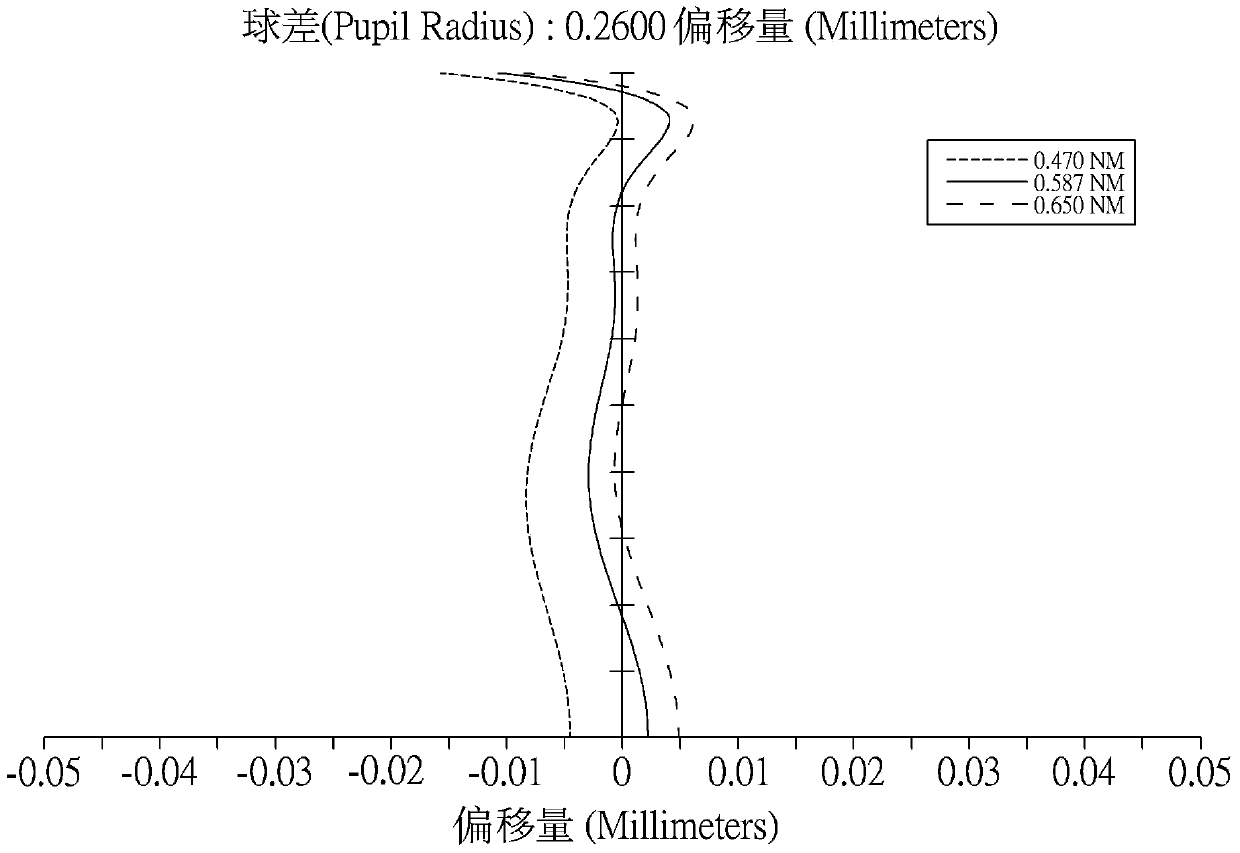
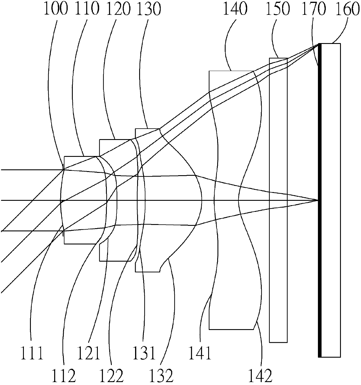
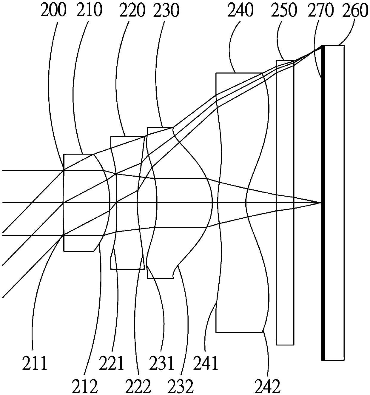
[0031] The invention provides an optical imaging lens. see figure 1 The optical imaging lens includes four lenses, which are arranged along the optical axis from the object side to the image side: a first lens 110 , a second lens 120 , a third lens 130 and a fourth lens 140 . Wherein, the first lens 110 has a positive refractive power; the second lens 120 has a negative refractive power; the third lens 130 has a positive refractive power; the fourth lens 140 has a negative refractive power, and its image side optical surface 142 is provide...


PUM


Abstract

The invention discloses an optical image-taking lens. The optical image-taking lens comprises four lenses, the four lenses are successively a first lens having positive focal power, a second lens having a negative focal power, a third lens having a positive focal power and a fourth lens having a negative focal power from the object side to the image side, and an optical face of the image side is provided with at least one inflection point. Each lens comprises at least one aspheric surface. The optical image-taking lens further comprises a diaphragm disposed between a photographed object and the second lens and an image sending assembly disposed on an imaging surface. A distance of the first lens from an object side optical surface to the imaging surface on an optical axis is TTL, an overall optical system focal length of the optical image-taking lens is f, a vertical distance between the optical axis and an intersection point projected on the imaging surface by a light ray which passes through the center of the diaphragm at an incident angle relative to the optical axis from an object side direction is Y1, and the optical image-taking lens meets a relational expression: 1.3<TTL/f<1.8, and 0.8<Y1/f<0.98. The optical image-taking lens has the good resolving power, can reduce the total length, and then can be applied to a camera, a mobile phone camera and the like which have good photographing purpose use demand.

Description

technical field [0001] The present invention relates to an imaging lens group, in particular to an imaging lens group composed of four lenses, which is used as an optical imaging lens for electronic products such as mobile phones. Background technique [0002] With the advancement of technology, the current trend of electronic product development is mainly toward miniaturization, such as digital cameras (Digital Still Camera), web cameras (Web Camera), mobile phone cameras (Mobile Phone Camera), etc. Users need smaller and low-cost cameras. In addition to the imaging lens group, it is also hoped to achieve an imaging lens group with good aberration correction capabilities, high resolution, and high imaging quality. [0003] Most of the early mobile phone lenses used a mixture of glass lenses and plastic lenses, such as 1G (G: glass), 2P (P: plastic) or 1G3P. Among them, 1G2P, such as US Patent No. 6,441,971, uses glass lenses for the first lens, and the second and third The...

Claims


Application Information

Patent Timeline
Patent Type & Authority Applications(China)
IPC IPC(8): G02B13/00G02B13/18G02B13/22G02B13/06G02B1/04
Inventor 郭瑞雄
Owner 彩晶光电科技(昆山)有限公司
Why Eureka
Try Eureka