Generator rotor de-excitation and overvoltage protection device

A technology of generator rotor and protection device, applied in emergency protection circuit device, emergency protection circuit device, circuit device for limiting overcurrent/overvoltage, etc., to avoid open circuit, overcurrent protection action, and demagnetization powerful effect

Inactive Publication Date: 2015-11-25
WUHU LANDZO ELECTRONICS TECH
View PDF1 Cites 1 Cited by
  • Summary
  • Abstract
  • Description
  • Claims
  • Application Information

AI Technical Summary

Problems solved by technology

[0002] The excitation power supply must be cut off quickly when there is a fault in the generator set or at the outlet of the generator and it is shut down normally. Since the rotor winding is a large inductance for energy storage, the excitation current The sudden change will inevitably cause a considerable transient overvoltage at both ends of the rotor winding, resulting in rotor insulation breakdown, so the rotor inductance must be demagnetized as soon as possible. Closing and other reasons will cause the generator to operate in non-full phase or with a large slip difference. Under these two operating conditions, severe overvoltage will be generated in the rotor winding, because at this time the energy of the grid and the excitation power supply can be transmitted to the generator. In the rotor winding, the energy transport exceeds the demagnetization energy of the demagnetization device. When all the fuses in the demagnetization device are blown, the rotor winding is open. At this time, the rotor winding is equivalent to a constant current source, and the generated overvoltage will break down the rotor. Winding insulation, causing damage to unit equipment

Method used


Image

  • Generator rotor de-excitation and overvoltage protection device

Examples


Embodiment Construction

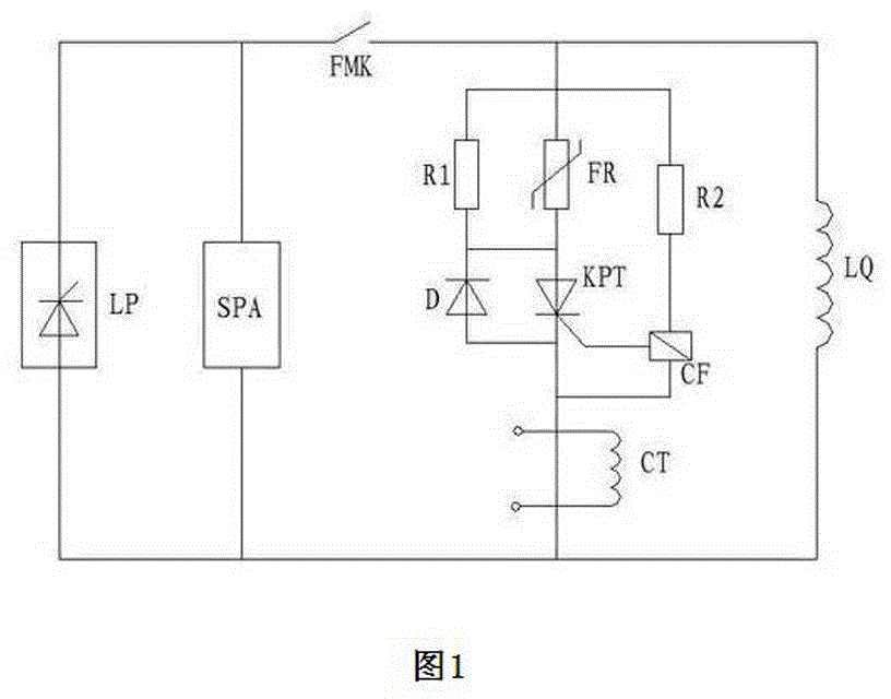
[0012] see figure 1 , a generator rotor de-excitation and overvoltage protection device, which includes de-excitation switch FMK, peak overvoltage absorber SPA, non-linear resistance FR, controllable silicon trigger CF, thyristor KPT, diode D, current mutual inductance CT, linear resistors R1 and R2, one end of the demagnetization switch FMK is connected to one end of the peak overvoltage absorber SPA and then connected to a rectifier power supply, and the other end is respectively connected to one end of the linear resistor R1, one end of the linear resistor R2 and one end of the non-linear resistor FR The other end of the linear resistor R1 is connected in parallel with the other end of the non-linear resistor FR, and then one end of the diode D and one end of the thyristor KPT are connected. another side. The other end of the diode D is connected to one end of the current transformer CT, and the other end of the current transformer CT is connected to the other end of the ...


PUM


Abstract

The invention provides a generator rotor de-excitation and overvoltage protection device which relates to an overvoltage protection device of a silicon controlled rectifier excitation system. The generator rotor de-excitation and overvoltage protection device comprises a de-excitation switch, a peak overvoltage absorber, a non-linear resistor, a silicon controlled rectifier trigger, a silicon controlled rectifier, a diode, a current transformer and linear resistors. One end of the de-excitation switch is connected with one end of the peak overvoltage absorber and then is connected with a rectification power supply, and the other end of the de-excitation switch is connected with one end of each linear resistor and one end of the non-linear resistor. The other end of one linear resistor is connected with the other end of the non-linear resistor in parallel and then is connected with one end of the diode and one end of the silicon controlled rectifier. The other end of the other linear resistor is connected with the silicon controlled rectifier trigger. The silicon controlled rectifier trigger is further connected with the other end of the silicon controlled rectifier, the other end of the diode and one end of the current transformer. The other end of the current transformer is connected with the other end of the peak overvoltage absorber and then is connected with a rotor winding. According to the invention, the de-excitation capability is strong, the de-excitation speed is high, the overvoltage protection action speed is high, an open circuit of the rotor winding is avoided, and the insulation breakdown accidents of the rotor winding are effectively prevented.

Description

technical field [0001] The invention relates to the technical field of generator rotor demagnetization and overvoltage protection, in particular to an overvoltage protection device for a thyristor rectification excitation system. Background technique [0002] The excitation power supply must be cut off quickly when the generator set or the outlet of the generator fails or is shut down normally. Since the rotor winding is a large inductance for energy storage, the sudden change of the excitation current will inevitably cause a considerable transient overvoltage at both ends of the rotor winding. , causing rotor insulation breakdown, so the rotor inductance must be demagnetized as soon as possible. For the thyristor rectification excitation system, the generator will not run in full phase or have a large slip due to non-full-phase or non-synchronous closing of the generator circuit. The difference is not running. Under these two operating conditions, severe overvoltage will b...

Claims


Application Information

Patent Timeline
Patent Type & Authority Applications(China)
IPC IPC(8): H02H7/06H02H9/04
Inventor 不公告发明人
Owner WUHU LANDZO ELECTRONICS TECH
Why Eureka
Try Eureka