Solder ball pump head for laser soldering

A solder ball and laser technology, applied in the direction of tin feeding device, welding equipment, metal processing equipment, etc., can solve problems such as difficult to realize, large frictional resistance, etc., to achieve guaranteed reliability, low manufacturing cost, and reduce random impossibility Effect

Active Publication Date: 2015-12-02
WUHAN LINGYUN PHOTOELECTRONICS SYST
View PDF8 Cites 18 Cited by
  • Summary
  • Abstract
  • Description
  • Claims
  • Application Information

AI Technical Summary

Problems solved by technology

[0015] In addition, the friction surface between the turntable 1 and the upper end cover 13 and the lower end cover 2 is relatively large, and the frictional resistance will be too large due to the comprehensive factors of manufacturing and installation. Therefore, it will be difficult to realize the function of judging the stuck ball by using the change of the motor load current

Method used


Image

  • Solder ball pump head for laser soldering
  • Solder ball pump head for laser soldering
  • Solder ball pump head for laser soldering

Examples


Embodiment Construction

[0040] The technical solutions in the present invention will be clearly and completely described below with reference to the accompanying drawings in the present invention.

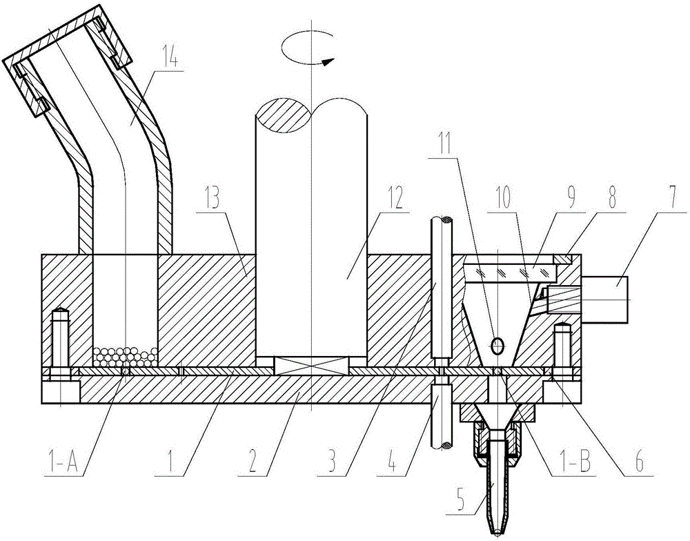
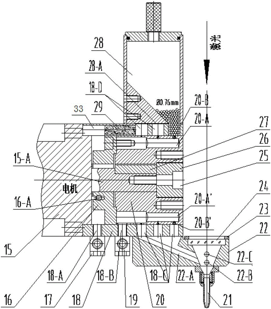
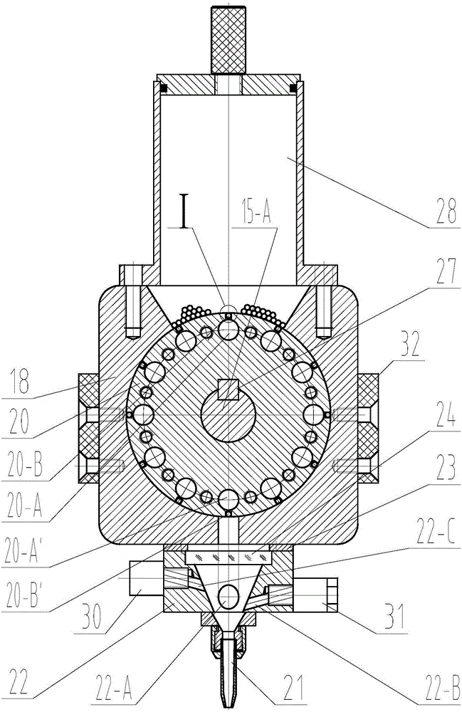
[0041] Please refer to Figure 2-4 , the present invention provides a solder ball pump head for laser soldering, the solder ball pump head for laser soldering includes an outer sleeve 18, a solder ball bucket 28 mounted on the outer sleeve 18, The rotor 20 in the sleeve 18 and the motor 15 for driving the rotor 20 to rotate.

[0042] An air gap 28-A whose width is smaller than the diameter of the solder balls and communicates with the inner cavity of the solder ball bucket 28 is provided between the bottom of the solder ball bucket 28 and the outer sleeve 18, and the air gap 28-A is used for introducing protective gas. The air gap 28-A is so arranged to allow the shielding gas to enter the solder ball barrel 28, and to prevent the solder balls in the solder ball barrel 28 from entering the air gap 28-A. ...


PUM


Abstract

The invention provides a solder ball pump head for laser soldering. The solder ball pump comprises an outer sleeve, a solder ball barrel installed on the outer sleeve, a rotor arranged in the outer sleeve and a motor driving the rotor to rotate. The outer wall of the cylindrical surface of the rotor is concaved inwards to form at least one ring of solder ball containing tank distributed circumferentially. The solder ball barrel is installed above the longitudinal plane where the solder ball containing tanks are located and communicated with the solder ball containing tanks. The lower portion of the outer sleeve is provided with ball falling channels communicated with a nozzle through a chute. When rotated to the lower portion, the solder ball containing tanks on the rotor are communicated with the ball falling channels; the solder ball containing tank at the upper end of the rotor is used for receiving a solder ball falling from the solder ball barrel, and the solder ball is closed in the solder ball containing tank when the rotor rotates, slides along the inner wall of the outer sleeve, and enters the corresponding ball falling channel of the outer sleeve till the solder ball containing tank moves to the lower portion of the rotor. According to the solder ball pump head, the manufacturing cost is low, machining precision can be easily guaranteed, and the fault that the ball gets stuck can be effectively reduced.

Description

technical field [0001] The invention relates to the field of laser automation, in particular to a tin ball pump head used for laser soldering. Background technique [0002] Common laser welding is to irradiate the object to be welded with a laser to make it undergo a physical process from melting to recrystallization. The term is called "physical phase transition", and its recrystallization process also includes "alloy phase transition". Even the occurrence of "chemical changes", etc., the finally obtained welded body, we call this welding form "laser fusion welding", and the welding mechanism is as follows: [0003] Physical phase transition: solid phase → liquid phasesolid phase [0004] Alloy phase transformation: For the welding of two different substances, A and B, when the phase change occurs, it will also be accompanied by chemical phase transformation. For example, the alloying elements in the A body will occur in the liquid phase. The combination of metal bonds...

Claims


Application Information

Patent Timeline
IPC IPC(8): B23K3/06B23K1/005
CPCB23K1/0056B23K3/0638
Inventor 韩小平林卿王锋
Owner WUHAN LINGYUN PHOTOELECTRONICS SYST
Why Eureka
Try Eureka