Laser precision de-weight system and method

A laser and precision technology, applied in laser welding equipment, welding equipment, metal processing equipment, etc., can solve problems such as affecting the service life of the rotor, affecting the working stability of the gyro instrument, and being unsuitable for the laser dynamic balance measurement method, to optimize the optical Structural design, reduce laser deduplication burr, the effect of the best deduplication effect

Active Publication Date: 2015-12-02
BEIJING INST OF AEROSPACE CONTROL DEVICES
View PDF8 Cites 15 Cited by
  • Summary
  • Abstract
  • Description
  • Claims
  • Application Information

AI Technical Summary

Problems solved by technology

However, this method has low balancing efficiency, poor positioning accuracy, high labor intensity, and low balancing accuracy. Frequent starting, weight removal, and stopping also affect the service life of the rotor
In addition, for the flexible gyro rotor with a special structure, due to the low strength of the flexible joint and the large force of manual degravity, it is easy to deform the ribs of the joint and directly affect the working stability of the gyro instrument; another way is to use laser Dynamic balance measurement and weight removal, but because the liquid floating gyro rotor can only detect the unbalanced position in the oil slick, it cannot be measured in high-speed rotation, so it is not suitable for laser dynamic balance measurement
Before the laser was used for balancing, it was reported abroad that electronic beam processing was used to achieve balance, but compared with the electrostatic gyroscope, because the electromagnetic field interference deflection is generated during the balancing process, and a vacuum system and a high-voltage system are also required, which limits its use. use

Method used


Image

  • Laser precision de-weight system and method
  • Laser precision de-weight system and method
  • Laser precision de-weight system and method

Examples


Embodiment

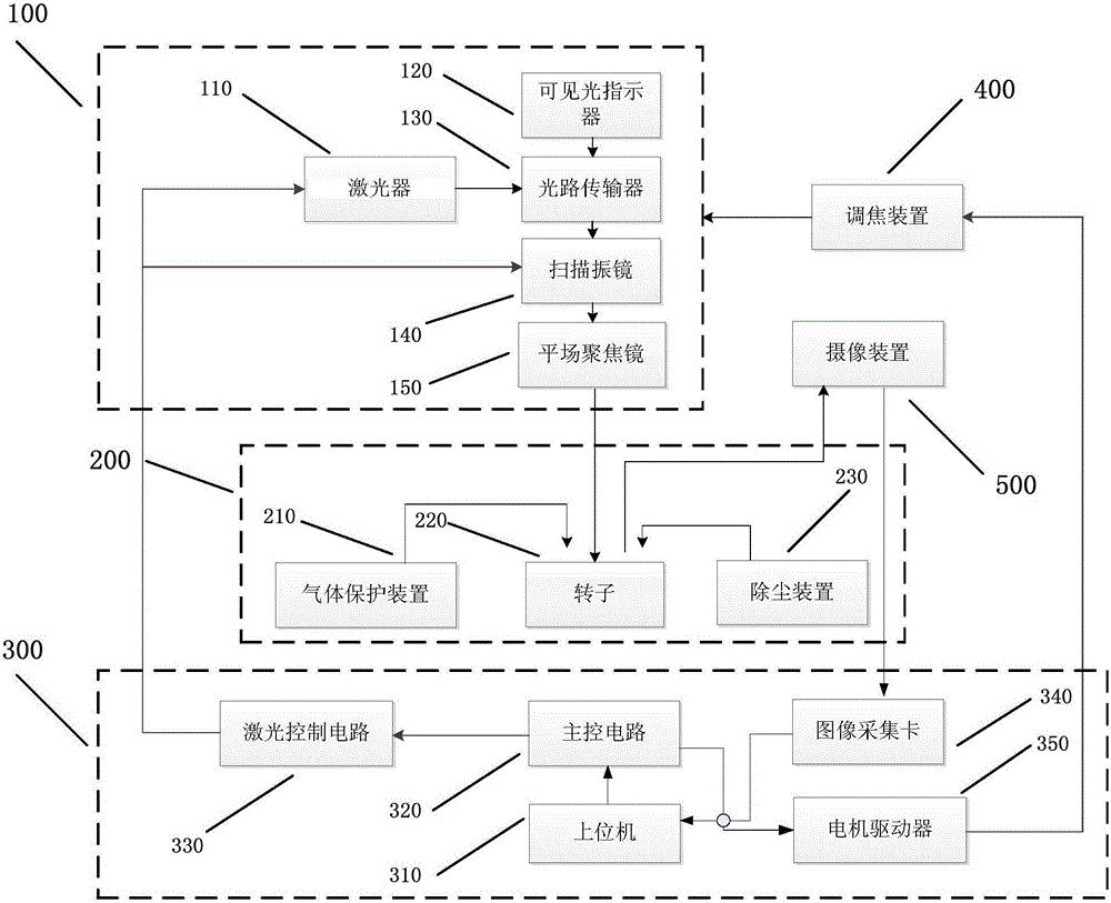
[0081] Attached below figure 1 A specific example of the present invention is described:

[0082] This example is mainly aimed at the laser precision de-weighting system to realize the function of rotor balance, which is used to improve the balance accuracy of rotating parts such as inertial navigation systems and jet engines, and is suitable for the precision machining fields of aviation, aerospace and military.

[0083] The components and features included in the system are: the laser 110 and the visible light indicator 120 emit lasers with wavelengths of 1064nm and 632.8nm respectively, wherein the average power of the 1064nm laser is 30W, and the average power of the 632.8nm laser is 10mW on the same optical axis. The optical path transmitter 130 includes a beam combiner and a beam expander. One side of the beam combiner is coated with a 1064nm anti-reflection coating, and the other side is coated with a 45° 632.8nm high-reflection coating, which is used to reflect the ind...


PUM


Abstract

The invention discloses a laser precision de-weight system. The system comprises a laser light path transmission unit, a work field, a laser circuit control unit, a focusing adjustment device and a photographic device, and the laser light path transmission unit transmits high-energy density laser to the work field; the laser circuit control unit comprises an upper computer, a master control circuit, a laser control circuit, an image acquisition card and a motor driver; the master control circuit sends direction and pulse instructions received from the upper computer into the motor driver, the motor driver sends direction and pulse signals to the focusing adjustment device, the position movement of the laser light path transmission unit is controlled, and the laser focal position is further controlled accurately. According to the laser precision de-weight system and method, the traditional electric drill de-weight balancing mode is replaced with the laser de-weight mode, defects that the traditional balancing mode is poor in location precision and low in de-weight precision are made up, the traditional complex de-weight process is simplified, a rotor does not need to be mounted and clamped multiple times, and the balancing efficiency of the rotor is improved.

Description

technical field [0001] The invention relates to a device that uses laser technology to complete the adjustment of the center of mass of the rotor so that it reaches a balanced state. Specifically, it relates to a laser precision weight removal system and method, which is mainly used to improve the balance precision of inertial navigation systems and jet engines. processing field. Background technique [0002] With the continuous improvement of the precision and stability of the inertial gyro instrument, the accuracy and process requirements for the dynamic balance of the gyro rotor are also increased. The deweighting balance is actually completed by changing the mass distribution of the rotor. In all precision machinery and instruments with high-speed rotating parts such as gyro motors, electric motors, jet engine moving parts, etc., the functional errors (such as drift effects on gyroscopes) and disturbing swings are often caused by residues in the rotating parts. caused b...

Claims


Application Information

Patent Timeline
IPC IPC(8): B23K26/36B23K26/142B23K26/14B23K26/03B23K26/046
CPCB23K26/032B23K26/046B23K26/14B23K26/361
Inventor 李广张琳刘佳何哲玺王军龙于文鹏王学峰
Owner BEIJING INST OF AEROSPACE CONTROL DEVICES
Why Eureka
Try Eureka