Pipe blank injection molding method and pipe blank mold for high-capacity plastic bottles

A technology for injection molding and plastic bottles, which is applied in the field of tube blank injection molding and tube blank mold for large-capacity plastic bottles. Effect

Active Publication Date: 2015-12-02
湖南昊兴机械科技有限公司
View PDF8 Cites 1 Cited by
  • Summary
  • Abstract
  • Description
  • Claims
  • Application Information

AI Technical Summary

Problems solved by technology

[0011] The purpose of the present invention is to propose a new one-step injection stretch blow molding method for the current domestic production of one-step injection stretch blow molding equipment, which has the problem that multi-station is difficult to ensure the quality

Method used


Image

  • Pipe blank injection molding method and pipe blank mold for high-capacity plastic bottles
  • Pipe blank injection molding method and pipe blank mold for high-capacity plastic bottles
  • Pipe blank injection molding method and pipe blank mold for high-capacity plastic bottles

Examples


Embodiment 1

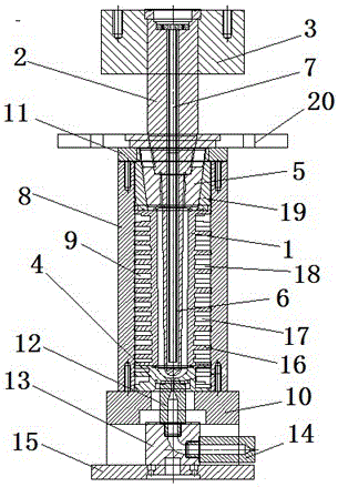
[0037] The cooling flow channel 9 formed between the core sleeve 8 and the outer surface of the tube embryo cavity 1 and the cavity bottom 4 is a labyrinth-like flow channel similar to a labyrinth, so that the cooling oil flows in the tube blank cavity and the bottom of the cavity. The outer periphery forms a labyrinth circulation cooling channel.

[0038] The labyrinth flow channel is an annular labyrinth flow channel formed by the combination of the circular groove 16, the notch 17 and the block 18, and there are more than two circular grooves 16 on the outer surface of the tube embryo cavity and the bottom of the cavity. There is a gap 17 between every two adjacent circular grooves, and a stopper 18 is arranged in each circular groove, and the stopper 18 is arranged next to the gap 17, so that the cooling medium flows from the mold core sleeve After the entrance of 8 flows in, it must go around the circular groove, and then enter the previous circular groove from the gap cl...

Embodiment 2

[0044] The part where the top of the first hot runner is in contact with the bottom mold of the cavity is provided with a heat insulation pad so that the high temperature of the first hot runner will not be transmitted to the bottom mold of the cavity. The heat insulation pad is a paper pad with a thickness of 0.5-2 mm.

[0045] Embodiment Three

Embodiment 3

[0047] The tube embryo mold core is also cooled by oil or water, and the cooling medium comes out of the oil temperature machine and is transported to the deep hole blind hole of the tube embryo core through the cooling pipe, and then passes through the cooling pipe and the periphery of the deep hole blind hole. Some gaps return to realize temperature-controlled cooling of the tube blank mold core.

[0048] Apparently, the above-mentioned embodiments are only to illustrate several examples of the present invention, any simple modification, replacement and adoption of vertical or other mold opening methods by any ordinary skilled in the art are within the protection scope of the present invention.


PUM

PropertyMeasurementUnit
thicknessaaaaaaaaaa

Abstract

The invention discloses a pipe blank injection molding method and a pipe blank mold for high-capacity plastic bottles. The injection molding method includes filling the temperature-control pipe blank mold with injection molding materials to form pipe blanks by means of injection molding, and is characterized in that the integral pipe blank mold is of a cooling structure with multiple flow channels, a pipe blank mold core and a pipe blank mold cavity are cooled in a temperature-control mode, and the temperatures of cooling media are controlled by temperature control equipment, so that the temperature of cooling oil of the pipe blank mold core is 50-60 DEG C under the control, and the temperature of cooling oil of the pipe blank mold cavity is 45-55 DEG C under the control; the hot flow channel of a bottom feed inlet is divided into three portions, and heat of each portion can be preserved differently, so that heat of residual materials which are not fed into the pipe blank mold cavity can be preserved, and the residual materials can be prevented from flowing outwardly. The pipe blank injection molding method and the pipe blank mold have the advantages that the integral pipe blank mold is of the cooling structure with the multiple flow channels, the temperatures of the different portions can be differently controlled by temperature control devices, accordingly, the molding temperatures of products can be effectively controlled, the molding quality of the products can be guaranteed, and the residual materials can be prevented from being hardened or flowing outwardly.

Description

technical field [0001] The present invention relates to a method and device for processing and molding plastic products, in particular to a method and device for injection molding tube blanks in the integrated production process of injection, stretching and blowing of large-capacity plastic bottles, and is mainly used for making large-capacity plastic bottles , It can also be used in the production of other high-demand plastic bottles and plastic containers. The invention belongs to the technical field of plastic processing manufacturing methods and equipment. Background technique [0002] With the rapid development of plastics and their products, plastic processing and manufacturing has gradually developed into a huge industrial cluster, and almost all walks of life are using plastic products. With the continuous development of the demand for plastic parts, the methods of plastic processing are also constantly updated. Injection molding is one of the main plastic molding ...

Claims


Application Information

Patent Timeline
Patent Type & Authority Applications(China)
IPC IPC(8): B29C45/26B29C45/27B29C45/73B29C45/78B29C49/06
CPCB29C45/26B29C45/2642B29C45/27B29C45/2737B29C45/78B29C49/06B29C2945/76531B29C2049/023
Inventor 李高虎李鑫水李晓清
Owner 湖南昊兴机械科技有限公司
Why Eureka
Try Eureka