Mechanically anchored connection node structure between concrete filled steel tube columns and reinforced concrete beams

A technology for reinforced concrete beams and concrete-filled steel tubular columns is applied in the field of mechanically anchored connection node structures, which can solve problems such as weakening of steel tubular columns, and achieve the effects of fast construction speed, clear force relationship, and reduced welding workload.

Active Publication Date: 2017-08-04
ARCHITECTURAL DESIGN RES INST OF GUANGDONG PROVINCE
View PDF8 Cites 0 Cited by
  • Summary
  • Abstract
  • Description
  • Claims
  • Application Information

AI Technical Summary

Problems solved by technology

However, this technology needs to perforate the steel pipe column, which will weaken the steel pipe column to a certain extent.

Method used


Image

  • Mechanically anchored connection node structure between concrete filled steel tube columns and reinforced concrete beams
  • Mechanically anchored connection node structure between concrete filled steel tube columns and reinforced concrete beams
  • Mechanically anchored connection node structure between concrete filled steel tube columns and reinforced concrete beams

Examples


Embodiment Construction

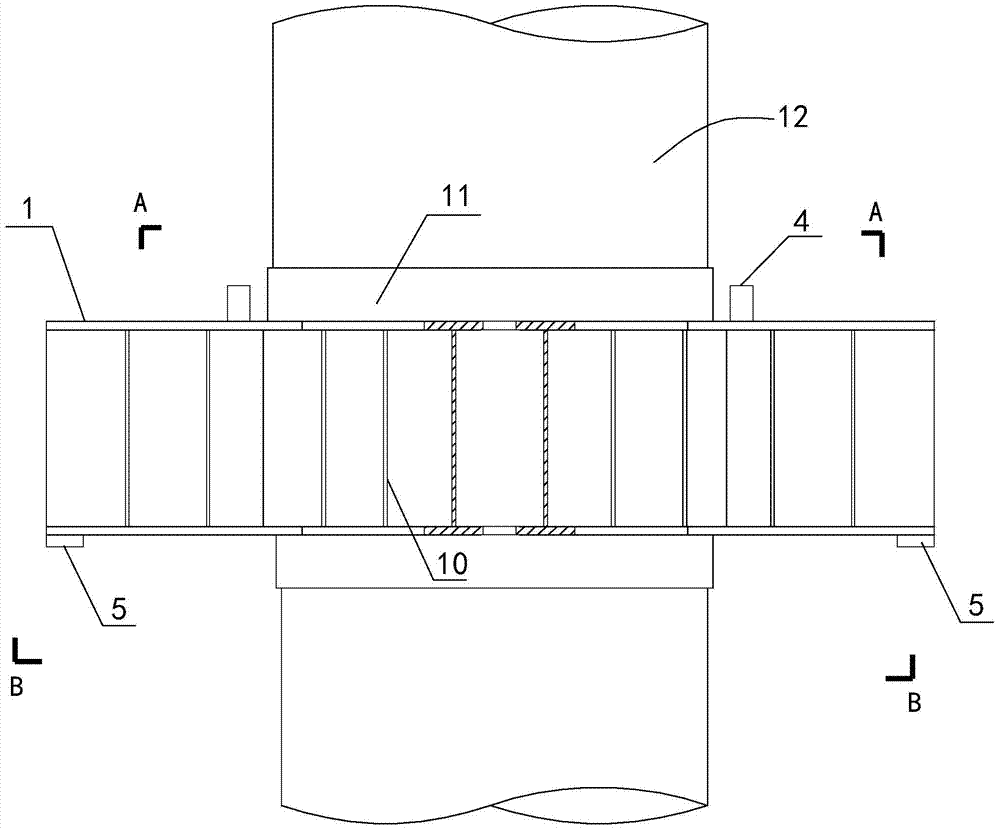
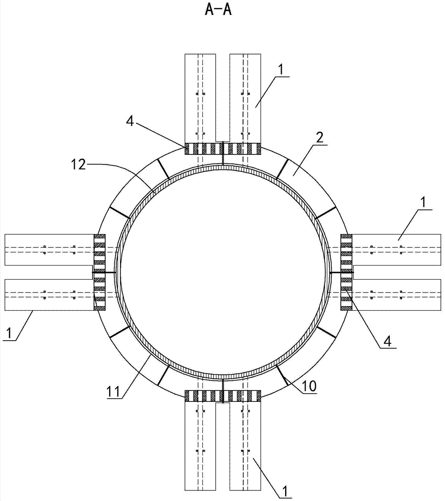
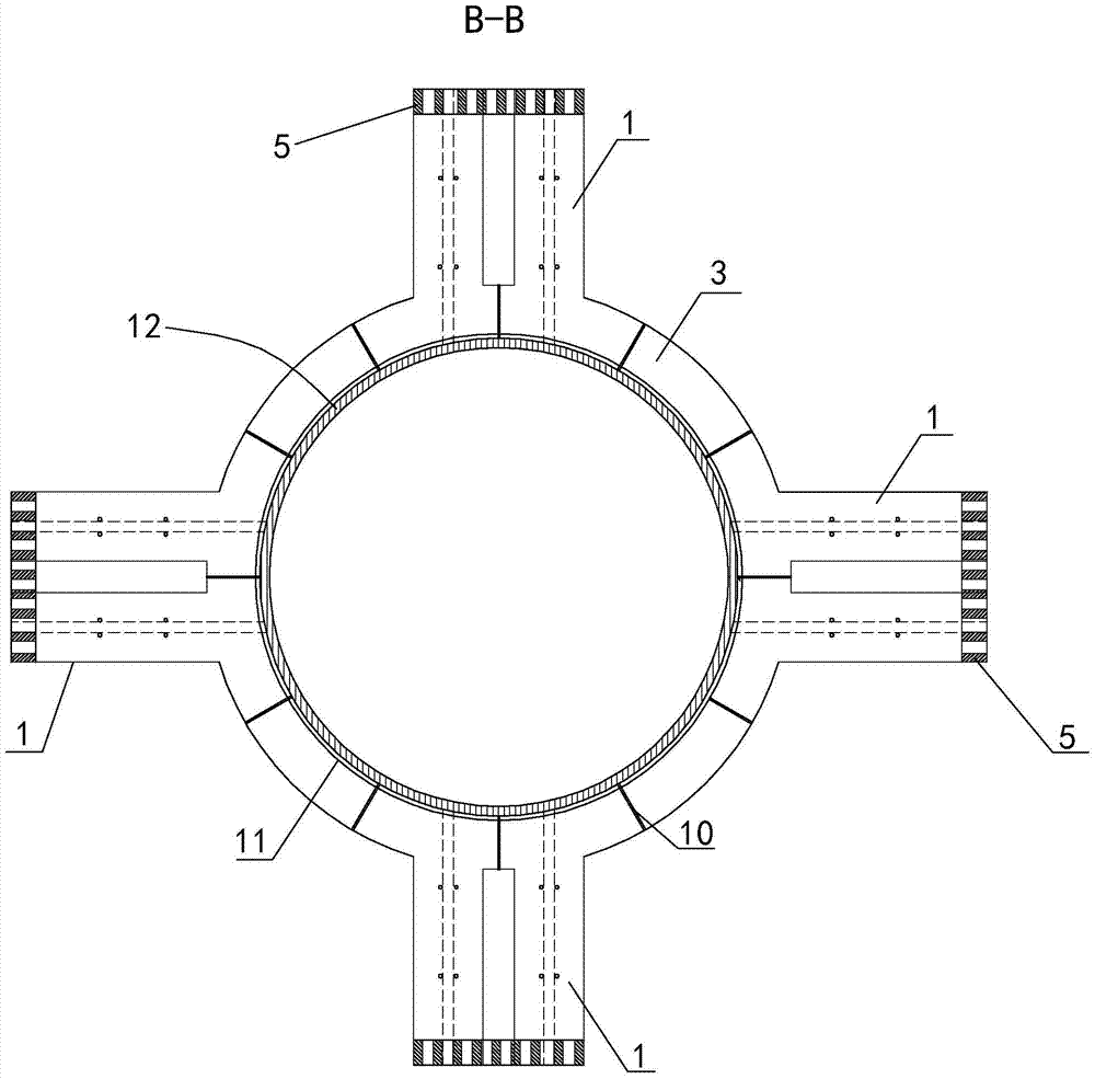
[0043] Such as Figure 1 to Figure 9 The mechanically anchored connection node structure between the concrete-filled steel tube column and the reinforced concrete beam is shown. Plates and connecting anchors.

[0044] The steel pipe column 12 is a vertical column, the beam gluten 6 and the beam bottom bar 7 are multiple horizontal beam longitudinal bars, the steel corbel 1 is four pairs of I-beams, and the steel corbel 1 has upper and lower flanges, Four pairs of I-beams are evenly arranged around the steel pipe column 12, each pair of steel corbels 1 is composed of two steel corbels 1 arranged in parallel, and the eight steel corbels 1 have the same structure and are all 700mm in length.

[0045] Since the beam reinforcement and the corbel are mechanically overlapped, the length of the steel corbel is taken as 0.6 times the anchorage length of the beam reinforcement. Considering that the diameter of the general beam reinforcement is less than 32 mm, the length of the steel c...


PUM


Abstract

The invention discloses a mechanical anchoring connection joint structure of a steel pipe concrete column and a reinforced concrete beam in a building structure. The joint structure comprises a steel pipe column, a beam surface rib, a beam bottom rib, a steel corbel, an upper horizontal ring plate, a lower horizontal ring plate and a connection anchoring machine, wherein the steel corbel is joist steel; the upper and lower wing edges, near the steel pipe column, of the steel corbel are respectively welded with the steel pipe column through the upper horizontal ring plate and the lower horizontal ring plate; the connection anchoring machine consists of an upper anchoring machine and a lower anchoring machine; the upper anchoring machine and the lower anchoring machine both have joint grooves; the upper anchoring machine is vertically welded on the upper horizontal ring plate; the end part, near the steel pipe column, of the beam surface rib is inserted into the joint groove of the upper anchoring machine after being provided with a nut and a washer; the lower anchoring machine is vertically and reversely welded at the bottom end of the steel corbel, and the welding position is far from the steel pipe column; and the end part, near the steel pipe column, of the beam bottom rib is inserted into the joint groove of the lower anchoring machine after being provided with a nut and a washer. The joint structure is simple in structure, stable in stress, quick in construction period, simple in construction and few in scene welding procedures, and can save steel materials.

Description

technical field [0001] The invention relates to a node structure in a building structure, in particular to a mechanically anchored connection node structure between a steel pipe concrete column and a reinforced concrete beam. Background technique [0002] The concrete-filled steel tube structure is developed on the basis of the steel-concrete structure. It uses the mutual restriction of the stress process of the two materials, the steel tube and the concrete, so that the steel tube concrete structure has high bearing capacity, good plasticity and toughness, and superior earthquake resistance and fire resistance. , material saving and short construction period. [0003] After years of practice and research, CFST structures have been widely used in various building structures, and experiments and theoretical research have also been carried out extensively and deeply. Especially in recent decades, with the rapid development of computers, the corresponding numerical calculation...

Claims


Application Information

Patent Timeline
Patent Type & Authority Patents(China)
IPC IPC(8): E04B1/58
Inventor 陈星张小良林扑强陈有德梁志红李宁张钧校龙秀海杨代恒余银银陈航王仕琪陈铸申苏森林谭堂州李剑
Owner ARCHITECTURAL DESIGN RES INST OF GUANGDONG PROVINCE
Why Eureka
Try Eureka