
Detection method for leakage of buried metal pipeline

A detection method and pipeline technology, applied in pipeline systems, mechanical equipment, gas/liquid distribution and storage, etc., can solve problems such as high false alarm rate, difficulty in realizing online real-time diagnosis, incomplete diagnosis information, etc., and achieve accurate leakage Detection effect

Active Publication Date: 2015-12-02
叶雷
View PDF4 Cites 7 Cited by
  • Summary
  • Abstract
  • Description
  • Claims
  • Application Information

AI Technical Summary

Problems solved by technology

Fault diagnosis based on the central database of the SCADA system, often due to incomplete diagnostic information and failure to optimize and update the diagnostic model parameters in time, etc. lead to weak evaluation ability of fault diagnosis and high false alarm rate
[0006] (2) Risk concentration
The fault diagnosis system based on the central database of the SCADA system is a centralized online real-time diagnosis architecture. Its advantage is that it is easy to carry out comprehensive fault diagnosis and analysis according to the global scheduling situation. It has sufficient processing power and high reliability, otherwise it is difficult to realize online real-time diagnosis
[0007] (3) Single diagnostic function
Since the pipeline adopts the operation mode of point-controlled line, its monitoring and diagnosis have the characteristics of space and time distribution, so on-site operators' smell, look, touch; check, measurement, reading and other information and diagnostic knowledge acquisition are very important for pipeline fault diagnosis, especially The discovery of seepage points is particularly important, and this is also the bottleneck of comprehensive fault diagnosis based on the central database of the SCADA system
[0008] (4) The leakage of buried metal pipelines can only be discovered through the gradient changes of pressure and flow when it occurs, and it has often developed into a major accident by then, and does not have the function of early warning and forecasting

Method used


Image

  • Detection method for leakage of buried metal pipeline
  • Detection method for leakage of buried metal pipeline

Examples


Embodiment Construction

[0027] The present invention is described below based on examples, but the present invention is not limited to these examples. In the following detailed description of the present invention, some specific details are described in detail. Those skilled in the art can fully understand the present invention without the description of these details. In order to avoid obscuring the essence of the present invention, well-known methods, processes, procedures, components and circuits are not described in detail.

[0028] In addition, those of ordinary skill in the art should understand that the drawings provided herein are for illustrative purposes, and the drawings are not necessarily drawn to scale.

[0029] Unless the context clearly requires, the words "including", "including" and other similar words in the entire specification and claims should be interpreted as inclusive rather than exclusive or exhaustive meanings; in other words, "including but not limited to" Meaning.

[0030] In...


PUM


Abstract

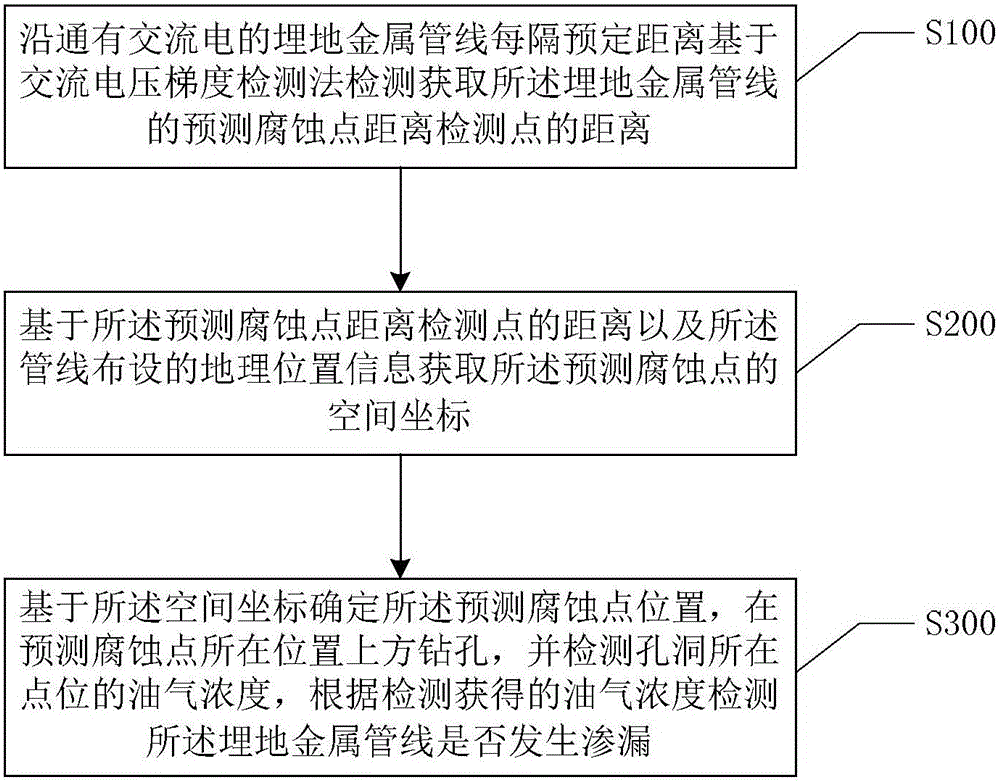
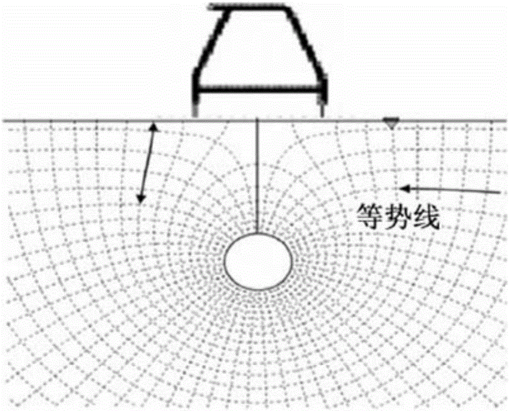
The invention discloses a detection method for leakage of a buried metal pipeline. According to the method, the earth surface current distribution state is detected on the basis of an alternating voltage gradient detection method, the distance between a predicted corrosion point and a detection point of the buried metal pipeline is acquired on the basis of the earth surface current distribution state, then the distance is converted into space coordinates of the predicted corrosion point on the basis of the geographical location information of the buried metal pipeline, and on-site hydrocarbon detection is performed on the basis of the space coordinates, so that leakage of the buried metal pipeline can be detected accurately in a nondestructive manner.

Description

Technical field [0001] The invention relates to the field of pipeline safety, in particular to a method for detecting leakage of buried metal pipelines. Background technique [0002] In the field of fault diagnosis for oil and gas pipelines and urban natural gas pipeline automation systems, especially in the field of leakage detection, the MORSAF system proposed by Italy's ENOTEAM Software Technologies, and the RTM (Real Time Model) and SCADA (SupervisoryControlAndDataAcquisition) commonly used in the oil and gas industry in China , Monitoring and data acquisition method) is the main leak detection method in this field. [0003] At present, whether RTM or SCADA is adopted in the leakage detection method of buried metal pipelines, the core is to use flow and pressure monitoring parameters to realize the quantification and location of leakage faults. [0004] The existing leak detection methods for buried metal pipelines based on detection parameters such as flow and pressure have the...

Claims


Application Information

Patent Timeline
IPC IPC(8): F17D5/06
Inventor 叶雷
Owner 叶雷
Learn More