Noncontact wheel multifunctional detection system

A detection system and multi-functional technology, applied in the direction of measuring devices, instruments, and optical devices, can solve the problems of slow test speed, low test efficiency, and difficulty in online detection, so as to improve test speed, facilitate data traceability, and facilitate The effect of replacement

Active Publication Date: 2015-12-02
浙江欧星环美汽车部件有限公司
View PDF13 Cites 7 Cited by
  • Summary
  • Abstract
  • Description
  • Claims
  • Application Information

AI Technical Summary

Problems solved by technology

[0002] For the measurement of wheels, the existing technology has various test methods and various test equipment, such as "a wheel detection device" (patent No. CN201410577641.3), "wheel rim runout detection device" (patent No. CN201410660869.9), "Improved hub detection device" (Patent No. CN201310654210.8), "Steel ring rim runout detection process and equipment structure" (Patent No. CN200810121548.6), "Determination of rim geometry and installation Method and equipment for dismantling tires" (patent number CN200710194611.4), "a method and equipment for determining the geometric dimensions of motor vehicle wheels (rim tire assembly) through non-contact detection" (patent number CN200810128017.X), etc. Public technology, but most of the existing technologies including the abo

Method used


Image

  • Noncontact wheel multifunctional detection system
  • Noncontact wheel multifunctional detection system
  • Noncontact wheel multifunctional detection system

Examples


Embodiment

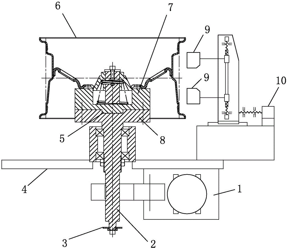
[0023] Embodiment: the non-contact wheel multifunctional detection system of the present invention, as attached figure 1 , attached figure 2 As shown, it includes a control system, a detection system, a data processing system, a shaft driving device 1 and a rotating shaft 2 driven by the shaft driving device 1. The rotating shaft 2 is sleeved with two tapered roller bearings, and the outer rings of the two tapered roller bearings are sleeved with bearings. The bearing seat is fixedly connected to the test bench body 4.

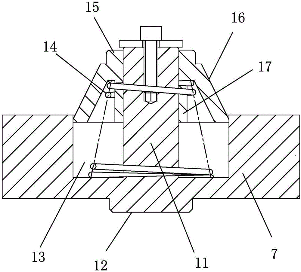
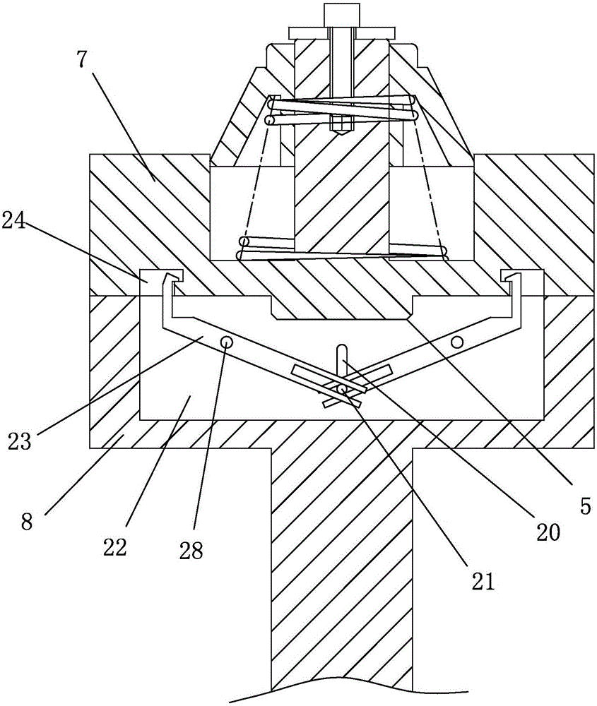
[0024] Rotating shaft 2 is arranged vertically, and round table 8 is arranged on the top, and test bench 7 is connected on the round table 8; There is a column 11 in the middle, and the column 11 is covered with a conical platform 15 that slides up and down along the column 11. The conical platform 15, the column 11 and the rotating shaft 2 are coaxially arranged; the diameter of the top of the conical platform 15 is smaller than the center hole of the wheel...


PUM


Abstract

The invention relates to a noncontact wheel multifunctional detection system comprising a control system, a detecting system, a data processing system, a shaft driving device, and a rotating shaft. The noncontact wheel multifunctional detection system is characterized in that the rotating shaft is vertically arranged; a circular table is arranged on the top of the rotating shaft and is connected with a test table; the top of the test table is a plane adapted to an installing surface of a wheel to be tested; a circular groove is disposed on the plane; a vertical column is disposed in the circular groove; a tapered table sleeves the vertical column and slides up and down along the vertical column; the tapered table, the vertical column, and the rotating shaft are arranged coaxially; the diameter of the top of the tapered table is less than that of the central hole of the wheel to be tested; the diameter of the bottom of the tapered table is greater than that of the central hole of the wheel to be tested; a spring is arranged between the tapered table and the bottom surface of the circular groove; and the detecting system includes a laser range finding sensor capable of moving horizontally and vertically. The wheel to be tested is easy and fast to position, install, and uninstall. The test table is convenient to replace in order that wheels in different specifications can be tested.

Description

technical field [0001] The invention relates to a test device, in particular to a non-contact wheel multifunctional detection system for online test wheels. Background technique [0002] For the measurement of wheels, the existing technology has various test methods and various test equipment, such as "a wheel detection device" (patent No. CN201410577641.3), "wheel rim runout detection device" (patent No. CN201410660869.9), "Improved hub detection device" (Patent No. CN201310654210.8), "Steel ring rim runout detection process and equipment structure" (Patent No. CN200810121548.6), "Determination of rim geometry and installation Method and equipment for dismantling tires" (patent number CN200710194611.4), "a method and equipment for determining the geometric dimensions of motor vehicle wheels (rim tire assembly) through non-contact detection" (patent number CN200810128017.X), etc. Public technology, but most of the existing technologies including the above-mentioned public t...

Claims


Application Information

Patent Timeline
IPC IPC(8): G01B11/00G01B11/02G01B11/08G01B11/30
Inventor 孙小明熊红兵
Owner 浙江欧星环美汽车部件有限公司
Why Eureka
Try Eureka