
Novel on-site equivalent darkroom measurement method

A measurement method and on-site technology, applied in the field of electromagnetic field and microwave, can solve the problems of restricting wide application, complex structure system, unsatisfactory effect, etc.

Active Publication Date: 2015-12-02
NAT UNIV OF DEFENSE TECH
View PDF7 Cites 3 Cited by
  • Summary
  • Abstract
  • Description
  • Claims
  • Application Information

AI Technical Summary

Problems solved by technology

In fact, in many cases, interference signals in ordinary environments have the characteristics of intermittent and amplitude fluctuations. Environmental interference signals cannot be effectively offset
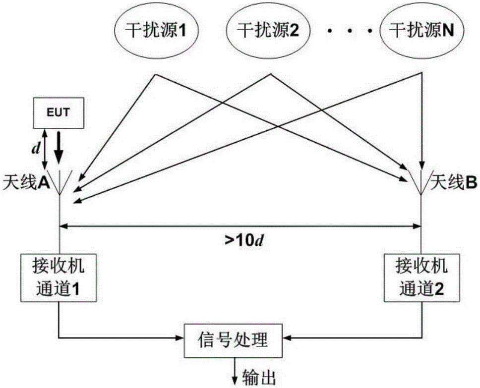
[0008] The virtual darkroom method based on noise cancellation has a great improvement over the time measurement method, but the effect is not ideal in actual use, mainly reflected in: ① In order to achieve the ideal accuracy, one of the receiving antennas needs to be placed far away from the EUT, Due to the inconsistency of the environmental interference at the location of the two receiving antennas, a large test error will be caused; ②The antennas are placed at a long distance, resulting in a long test cable, which is not feasible in operation and also affects the measurement accuracy; ③When the environment exists When the EUT radiates signals with the same frequency and high intensity components, the interference suppression effect is not obvious
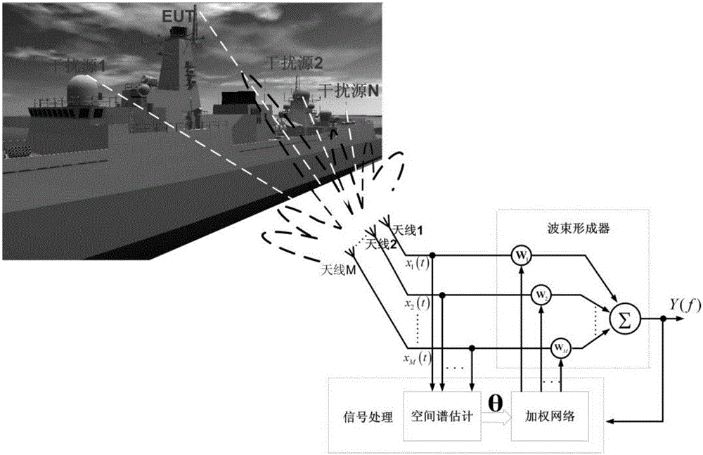
[0009] The interference suppression method based on array signal processing adopts a multi-channel system, its structure system is relatively complex, the design and implementation is difficult, and the hardware development cost is high, which limits its wide application

Method used


Image

  • Novel on-site equivalent darkroom measurement method
  • Novel on-site equivalent darkroom measurement method
  • Novel on-site equivalent darkroom measurement method

Examples


Embodiment 1

[0102] A computer simulation example is used to illustrate the effectiveness of the method of the present invention.

[0103] Such as Figure 5 Shown is a schematic diagram of the simulation configuration of this embodiment.

[0104] Take the array element spacing d=300mm, suppose there are four signals in the space, one of which is the EUT radiation signal (signal under test), and the other three are environmental interference signals with different systems. The mathematical form is as follows:

[0105] S E U T ( t ) = A 0 s i n 2 π f 0 ...

Embodiment 2

[0109] The specific process of verifying the effectiveness of this method through experiments will be introduced below. The experimental site configuration is as follows: Figure 7 As shown, in order to ensure the accuracy of the results, the experiment is carried out in a microwave anechoic chamber, the purpose is to shield the interference outside the experimental frequency band. Place the transmitting antenna and receiving antenna at the calibrated position, and the working frequency band of the antenna is 200MHz-1GHz. The principle of position calibration is to make the antenna of the simulated EUT transmit in the direction of the receiving antenna array, and the transmitting antenna of the simulated interference source forms a certain angle with the normal direction of the receiving antenna array. After the antenna is placed, the laser range finder and goniometer are used for position calibration. Signal source 1 and signal source 2 respectively simulate and generate EU...


PUM


Abstract

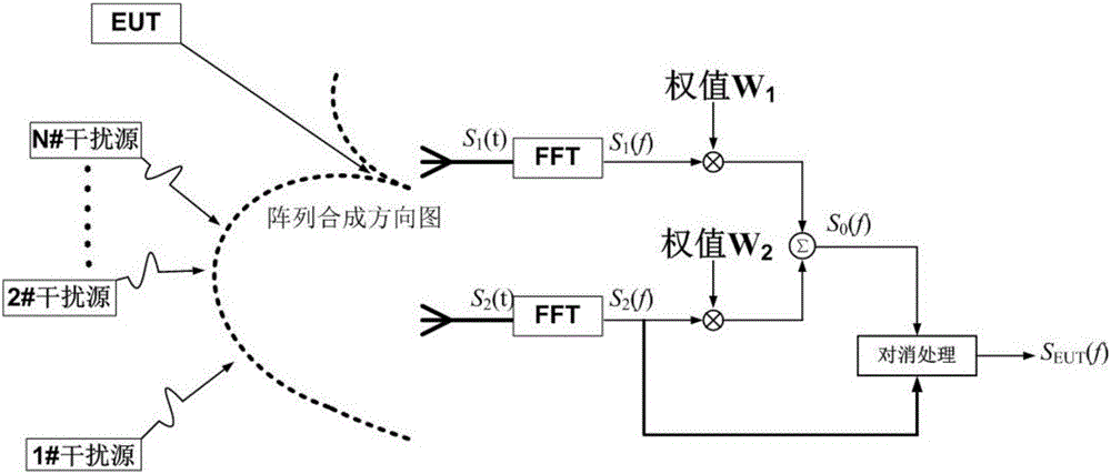
Disclosed is a novel on-site equivalent darkroom measurement method. Fourier transforms are performed on signals received by two antennas firstly, a zero point occurs in a directional diagram on a frequency domain by utilizing weight values and through combination with the directional diagram of a binary antenna array, the zero point is aligned with a signal direction of arrival (DOA) of equipment under test (EUT), an array output S<0>(f) only contains an interference component, signals S<1>(f) and S<2>(f) received by single antennas comprise EUT signal components and also comprise interference components, and the interference components in the array output S<0>(f) and the signals S<1>(f) and S<2>(f) are highly relevant, so the interference components in the S<1>(f) and S<2>(f) can be removed by utilizing cancellation processing, and then a signal of the EUT is obtained. Based on an advanced signal processing technology, through adoption of a double-channel system, and through combination of spatial filtering and a signal correlation processing method, when a test is performed on site, an equivalent darkroom environment can be obtained, on-site environment interferences are filtered, and a real radiation characteristic of the EUT is obtained.

Description

technical field [0001] The invention relates to the field of electromagnetic field and microwave technology, in particular to a method for performing electromagnetic radiation emission testing in a field environment. Background technique [0002] For large electronic equipment, field testing is usually used to find electromagnetic interference problems. But on-site radio, TV, mobile phones and other potential sources of radiation can seriously interfere with test accuracy. Usually, the level of the signal sent by it usually exceeds the standard limit by 30-40dB. This kind of environmental interference level submerges the transmitted signal of the equipment under test (EquipmentUnderTset, EUT), which will lead to long test time, large test error, and misinterpretation of environmental interference. It is considered to be adverse consequences such as the EUT signal, and the electromagnetic radiation of the EUT cannot be accurately measured, resulting in a diagnostic error. M...

Claims


Application Information

Patent Timeline
IPC IPC(8): G01R31/00
Inventor 卢中昊周东明李高升覃宇建黄纪军刘继斌薛国义刘培国
Owner NAT UNIV OF DEFENSE TECH
Learn More