Fuel battery shell and fuel battery device with stable output power

A fuel cell and casing technology, which is applied in the field of fuel cell devices and fuel cell casings, can solve problems such as power consumption, unstable current output, and unstable power supply, and achieve reduced output voltage, reduced conduction resistance, and improved The effect of stability

Active Publication Date: 2015-12-02
苏州讴德新能源发展有限公司
View PDF7 Cites 2 Cited by
  • Summary
  • Abstract
  • Description
  • Claims
  • Application Information

AI Technical Summary

Problems solved by technology

During the reaction process, the reactants will stay in the electrolyte, causing the reaction efficiency to decrease, resulting in unstable current output
At the same time, when the battery is discharged at high power for a long time, the temperature of the battery will increase. The increase in the temperature of the battery will increase the corrosion of the anode and the hydrogen evolution reaction. Hidden danger
[0003] The Chinese invention patent with application number 201110001792.0 and publication number CN102456939A discloses an improved large-capacity magnesium-air battery, which can solve the above-mentioned current output and temperature rise problems to a certain extent, but its electrolyte is equipped with an external circulation electrolyte circulation pipeline The electrolyte circulation pipeline is equipped with a circulating power pump, a cooling heat exchanger and a purifier. The structure is complex. Whether it is starting or running, it will continue to consume electric energy, which will greatly affect the power output capacity of the battery and the output power is not enough. Stablize
[0004] In addition, the use of the cooling heat exchanger in this technical solution will cause a large temperature difference between the reaction chamber and the external electrolyte, so that the output voltage of the reaction fluctuates greatly and the power supply is unstable.

Method used


Image

  • Fuel battery shell and fuel battery device with stable output power
  • Fuel battery shell and fuel battery device with stable output power

Examples


Embodiment Construction

[0024] Below, in conjunction with accompanying drawing and specific embodiment, the present invention is described further:

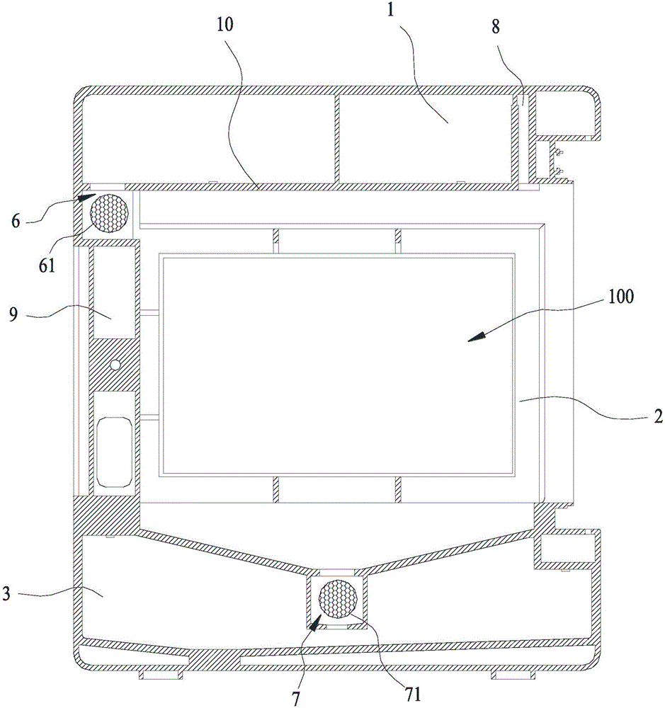
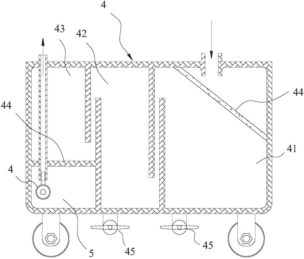
[0025] Such as Figure 1~2 The shown fuel cell housing includes a first storage tank 1 for electrolyte heat exchange, an electrochemical reaction chamber 2 for electrolyte reaction, and an electrochemical reaction chamber for accommodating reactants and electrolysis. A liquid mixture containing chamber 3, a filter device 4 for filtering reactants, and a second storage tank 5 for containing the reacted and filtered electrolyte, the first storage tank 1 is connected to the electrochemical reaction chamber through the first communication part 6 2, the electrochemical reaction chamber 2 communicates with the mixture storage chamber 3 through the second communication portion 7, and the mixing storage chamber communicates with the second storage tank 5 through the filter device 4.

[0026] Through the setting of the first communication part 6 and the second ...


PUM


Abstract

The invention discloses a fuel battery shell which comprises a first storage box for electrolyte heat exchange, an electrochemical reaction cavity for electrolyte reaction, a mixture accommodating cavity for accommodating reactants and electrolyte, a filtering device for filtering the reactants and a second storage box for accommodating reacted and filtered electrolyte, wherein the first storage box, the electrochemical reaction cavity, the mixture accommodating cavity, the filtering device and the second storage box are arranged in sequence from top to bottom; the first storage box is communicated with the electrochemical reaction cavity through a first communicating part; the electrochemical reaction cavity is communicated with the mixture accommodating cavity through a second communicating part; the mixture accommodating cavity is communicated with the second storage box through the filtering device. The invention further discloses a fuel battery device with stable output power, which adopts the fuel battery shell. By a simple structure, the fuel battery shell can automatically discharge the reactants, so that the phenomenon that the output power is unstable due to the continuous influence of the reactants on the electrolyte is avoided.

Description

technical field [0001] The present invention relates to a fuel cell, in particular to a fuel cell shell, and also relates to a fuel cell device with a stable output power using the fuel cell shell. Background technique [0002] A fuel cell is a power generating device that directly converts the chemical energy present in fuel and oxidant into electrical energy. For example, the aluminum and magnesium alloy fuel cell disclosed by the Chinese invention patent with the application number 201010525678.3, in the electrochemical reaction of the magnesium aluminum alloy fuel cell, the sheet metal anode is fixed in the reaction chamber, and the magnesium aluminum alloy anode and the air electrode are in the electrolyte The charge output is generated during the reaction process. During the reaction process, the reactants will stay in the electrolyte, causing the reaction efficiency to decrease, resulting in unstable current output. At the same time, when the battery is discharged a...

Claims


Application Information

Patent Timeline
Patent Type & Authority Applications(China)
IPC IPC(8): H01M8/04H01M8/24
CPCH01M8/04201H01M8/04208H01M8/249Y02E60/50
Inventor 马润芝施建
Owner 苏州讴德新能源发展有限公司
Why Eureka
Try Eureka