A falling film evaporator

A falling-film evaporator and evaporation zone technology, applied in the field of falling-film evaporators, can solve the problems of low steam heating efficiency, limited heating temperature, increased risk factor, etc., and achieve easy assembly and maintenance, high heating and cooling efficiency, and reduced equipment The effect of manufacturing cost

Active Publication Date: 2017-01-18
上海中科易成新材料技术有限公司
View PDF4 Cites 0 Cited by
  • Summary
  • Abstract
  • Description
  • Claims
  • Application Information

AI Technical Summary

Problems solved by technology

However, the high-temperature steam heating method has inherent disadvantages. First, the heating temperature is limited. If the temperature is too high, the equipment cost will be too high and the risk factor will increase; Long-term high-temperature steam atmosphere is easy to cause corrosion and damage to equipment; Fourth, steam heating efficiency is low and energy consumption is high

Method used


Image

  • A falling film evaporator
  • A falling film evaporator

Examples


Embodiment Construction

[0025] The present invention will be further described below in conjunction with specific embodiments and accompanying drawings.

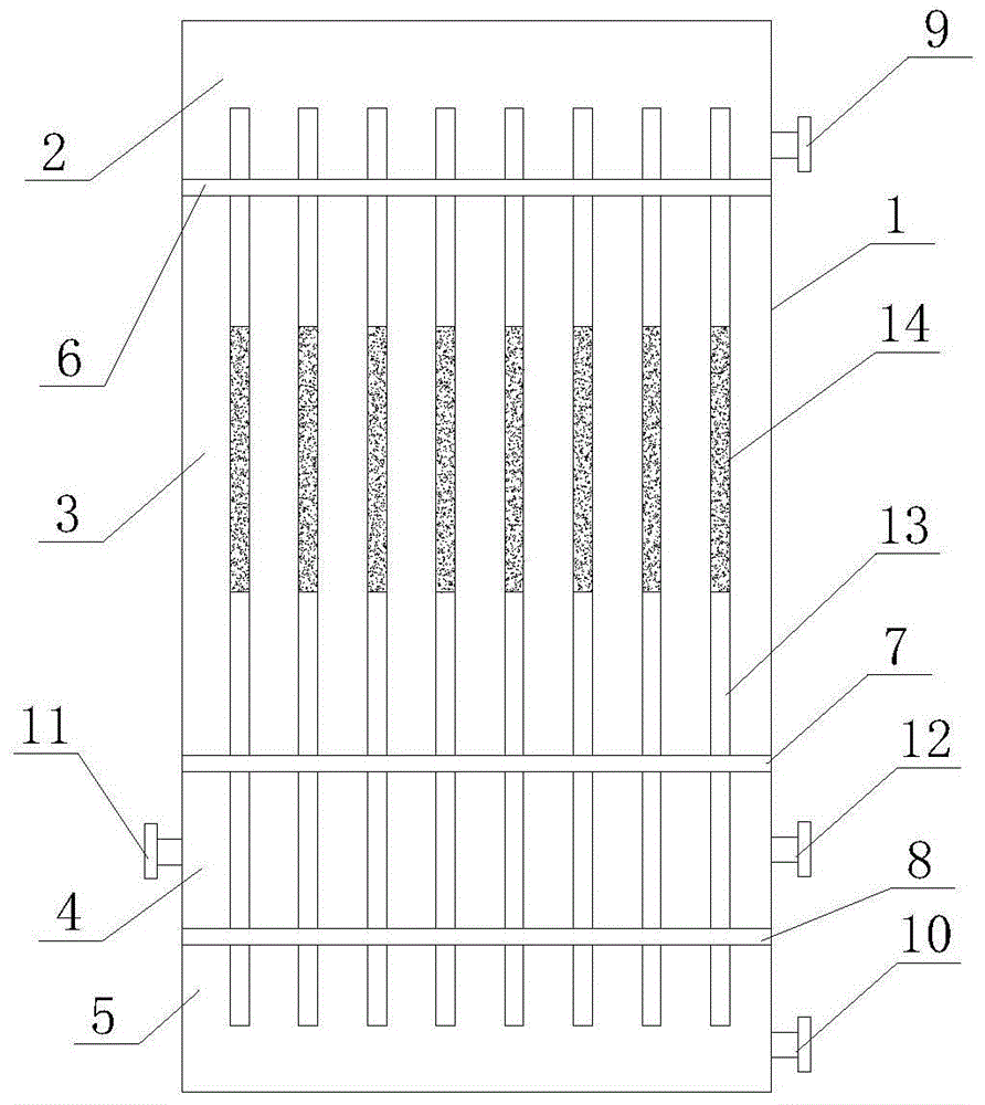
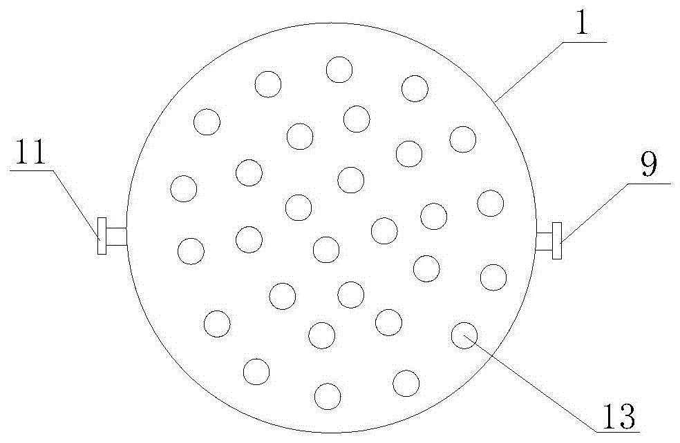
[0026] Such as figure 1 and figure 2 As shown, a falling film evaporator includes a closed shell 1 . The shell 1 is sequentially divided into a feed area 2 , an evaporation area 3 , a cooling area 4 and a discharge area 5 from top to bottom. The feed area 2 and the evaporation area 3 are separated by a horizontal upper end plate 6, the evaporation area 3 and the cooling area 4 are separated by a horizontal middle end plate 7, and the cooling area 4 and the discharge area 5 are separated by a horizontal lower end Plate 8 separates. A feed port 9 is provided on the side wall of the housing 1 located in the feed area 2, a discharge port 10 is provided on the side wall of the housing 1 located in the discharge area 5, and a discharge port 10 is provided on the side wall of the housing 1 located in the cooling area 4. There are symmetrical cooling ...


PUM


Abstract

The invention relates to a falling-film evaporator, belonging to the field of heat exchangers. The falling-film evaporator comprises an enclosed shell, wherein the interior of the shell is successively divided, from top to bottom, into four areas, i.e. a feeding area, an evaporation area, a cooling area and a discharging area, by an upper end plate, a middle end plate and a lower end plate; the side wall of the shell in the feeding area is provided with a feed inlet; the side wall of the shell in the discharging area is provided with a discharge outlet; the side wall of the shell in the cooling area is symmetrically provided with a cooling water inlet and a cooling water outlet; a plurality of heat exchange pipes are vertically arranged inside the shell; the top ends of the heat exchange pipes penetrate the upper end plate located in the feeding area; the lower ends of the heat exchange pipes penetrate the lower end plate and are then positioned in the discharging area; and the outer walls of the heat exchange pipes in the evaporation area are coated with an electroheating coating. The falling-film evaporator provided by the invention has simple structure, excellent evaporation efficiency and a wide application scope and is applicable in environments with harsh working conditions like high temperature, high pressure, strong acid and alkali corrosion.

Description

technical field [0001] The invention relates to the field of heat exchangers, in particular to a falling film evaporator. Background technique [0002] Falling film evaporators are widely used in the concentration and evaporation of production liquids in pharmaceutical, food, light industry, petrochemical, metallurgical and other industries. At present, most falling film evaporators use high-temperature steam to circulate outside the evaporation tube, and use tube wall heat exchange to heat and evaporate liquid. However, the high-temperature steam heating method has inherent disadvantages. First, the heating temperature is limited. If the temperature is too high, the equipment cost will be too high and the risk factor will increase; Long-term high-temperature steam atmosphere is easy to cause corrosion and damage to equipment; Fourth, steam heating efficiency is low and energy consumption is high. Contents of the invention [0003] The purpose of the present invention is...

Claims


Application Information

Patent Timeline
Patent Type & Authority Patents(China)
IPC IPC(8): B01D1/22
Inventor 黄政仁宇德海裴冰冰
Owner 上海中科易成新材料技术有限公司
Why Eureka
Try Eureka