Drying chamber air distribution structure capable of efficiently dehumidifying

A drying room and air distribution technology, applied in the direction of dehydration/drying/thickened sludge treatment, etc., can solve the problems of high consumption of auxiliary fuel, low solid content, large transportation volume, etc., and achieve energy consumption reduction and simple and reasonable design Effect

Active Publication Date: 2015-12-09
DONGGUAN DONGYUAN ENVIRONMENTAL TECH CO LTD
View PDF3 Cites 2 Cited by
  • Summary
  • Abstract
  • Description
  • Claims
  • Application Information

AI Technical Summary

Problems solved by technology

According to incomplete statistics, my country has nearly a thousand waterworks and sewage treatment plants that have been built, are under construction, and are planned to be built. The sewage of these waterworks will produce a large amount of sludge after being treated by existing technologies. The sludge is huge. Moreover, most of the pollutants removed from the sewage are accumulated in the sludge. If a large amount of sludge is not properly disposed of, it will inevitably cause serious secondary pollution.
At present, the methods of sludge disposal mainly include landfill, land use and incineration, etc. Direct landfill will occupy a large amount of land, and the filtrate will pollute groundwater; The mud contains harmful components and other reasons, which are greatly restricted; as a resource utilization method, the sludge is used as a fuel for energy supply, but this treatment method needs to reduce the moisture content of the sludge to 30%-40% %, otherwise the sludge with high water content will have low calorific value due to its low solid content, which will consume a large amount of auxiliary fuel, and the treatment cost will be significantly higher

Method used


Image

  • Drying chamber air distribution structure capable of efficiently dehumidifying
  • Drying chamber air distribution structure capable of efficiently dehumidifying

Examples


Embodiment Construction

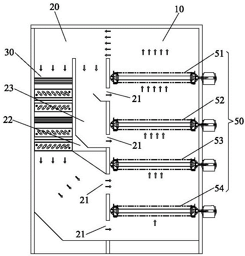
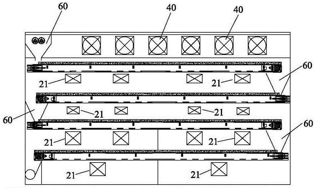
[0024] The invention is like figure 1 and figure 2 It is shown that a dry room can be efficient and dehumidified, including the first chamber 10, the second cavity room 20, the heat pump 30, the circulating fan 40, and the plural layer.in:

[0025] The first chamber 10 is connected above the second cavity room 20.

[0026] The heat pump 30 is installed on the 10 side walls of the first cavity chamber; the plural mesh zone 50 includes the first layer of the net zone 51, the second layer of the net zone 52, the third layer of the net zone 53, and the fourth layer net zone 54.The plural mesh belt 50 is installed in the second cavity room 20 in the secondary chamber, and the top of the top 50 of each net zone is set up above the top 50 of the sludge 60 that is used to put the sludge 60 on the net.

[0027] The circulating fan 40 has a total of multiple, and the plural cycle fan 40 is installed above the first layer of net zone 51.

[0028] On the side wall of the second cavity room, t...


PUM


Abstract

The invention discloses a drying chamber air distribution structure capable of efficiently dehumidifying, which comprises a first cavity, a second cavity, a heat pump, a circulation fan and a plurality of layers of net belts with meshes for conveying sludge; the first cavity is communicated with the space above the second cavity; the heat pump is arranged in the first cavity; the net belts are arranged in the second cavity; the circulation fan is arranged above the net belt at the top layer; vents aiming at all layers of net belts are formed in the side wall of the second cavity; an air guide plate extends on the side wall of the second cavity to the first cavity; an air flue communicated to the vent between two layers of net belts at the top is formed between the air guide plate and the side wall of the second cavity; one part of hot air generated by the heat pump returns back to the heat pump by the net belt at the top layer while the other part enters the vent between two layers of net belts at the top. Therefore, by adopting a hot air partition circulation mode, uniform distribution of air speed and air volume in the drying chamber is ensured, power consumption is reduced and the whole air distribution structure is simple, reasonable, energy-saving and efficient.

Description

Technical field [0001] The present invention involves technology in the field of drying equipment, especially a drying room in a dry -dehumidified drying room. Background technique [0002] With the continuous progress of human society, human beings are facing two major problems in environmental pollution and shortage of resources.According to incomplete statistics, my country has nearly a thousand households that have been completed and under construction and proposed tap water plants and sewage treatment plants. The sewage of these tap water plants will produce a large amount of sludge after the existing technology treatment. These sludge volume is huge. And most of the pollutants removed in sewage are gathered in sludge. If a large amount of sludge is not properly disposed of, it will inevitably cause severe secondary pollution.At present, the method of sludge disposal mainly includes landfills, land use and incineration, etc. Direct landfills will occupy a large amount of lan...

Claims


Application Information

Patent Timeline
IPC IPC(8): C02F11/12
Inventor 肖应东
Owner DONGGUAN DONGYUAN ENVIRONMENTAL TECH CO LTD
Why Eureka
Try Eureka