
Cooling system of power assembly

A cooling system and powertrain technology, applied in the direction of engine cooling, liquid cooling, coolant flow control, etc., can solve the problems of insufficient water pump capacity, cooling system distribution, waste, etc., to achieve improved cooling effect, reasonable control, The effect of reducing energy consumption

Inactive Publication Date:
View PDF4 Cites 25 Cited by
  • Summary
  • Abstract
  • Description
  • Claims
  • Application Information

AI Technical Summary

Problems solved by technology

These have caused the water flow demand of the entire cooling system to increase. At the same time, the increase in heat exchangers has led to the problem of the vehicle's cold start and warm-up speed and the heating of the heater in winter.
[0003] Due to the complexity of the water flow branches in the existing cooling system, the capacity of the water pump is insufficient, and there are problems of slow heating and poor heating effect. Similarly, due to the limitation of water flow, there is a problem of insufficient cooling capacity for the oil cooling system
Since heat exchangers such as heaters and gearbox oil coolers have different water flow requirements in different environments, most cooling systems currently do not distribute and adjust the flow of the entire cooling system according to demand, resulting in unnecessary waste
For example, when the gearbox oil is not cooled, there is still water flowing through it, which will reduce the flow of warm air and small circulating water, reduce the warm-up speed and heating effect, etc.

Method used


Image

  • Cooling system of power assembly

Examples


Embodiment Construction

[0044] The technical solution of the present invention is described in detail below through the examples, and the following examples are only exemplary and can only be used to explain and illustrate the technical solution of the present invention, rather than being interpreted as a limitation to the technical solution of the present invention.

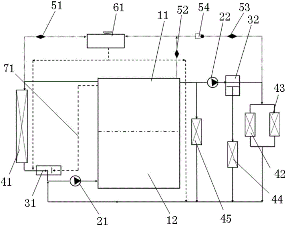
[0045] The invention provides a powertrain cooling system, such as figure 1 As shown, it includes an engine, a first cooling water pump 21, a radiator 41, a second cooling water pump 22, a first thermostat 31, a second thermostat 32, an oil cooler 45, a transmission oil cooler 44, a warmer Fan, connecting pipeline, expansion kettle 61 , first throttle valve 51 , second throttle valve 52 , third throttle valve 53 and one-way valve 54 .

[0046] In the present application, the engine includes an engine cylinder head 11 and an engine block 12, wherein the engine cylinder head is provided with a water outlet, and the engine block is provid...


PUM


Abstract

The invention relates to a cooling system of a power assembly. The cooling system comprises an engine, a first cooling water pump, a radiator, a second cooling water pump, a first thermostat, a second thermostat, an engine oil cooler, a gearbox oil cooler, a warm air blower and a connecting pipeline. By means of the cooling system of the power assembly, it is guaranteed that an engine is warmed up rapidly during cold engine starting, the whole vehicle major cycle and the unnecessary minor cycle at the low temperature can be closed through the first thermostat and the second thermostat, and more water flow circulates between an engine cylinder and a cylinder cover through an engine minor cycle pipeline; and heat exchange is reduced, and the engine warming-up speed is increased. When the temperature of the water of the engine is low, the minor cycle of a gearbox oil cooling system is reduced at the low temperature through the second thermostat so that it can be guaranteed that the gearbox oil does not exchange heat with the cooling water of the engine at the low temperature; and the oil temperature of a gearbox is increased more rapidly, and then a better lubrication effect is achieved.

Description

technical field [0001] The invention belongs to the technical field of automobile cooling systems, in particular to a cooling system of a power assembly. Background technique [0002] With the development of powertrain technology, the circuit of the cooling system is becoming more and more complex. With the increase of engine power, the load of the cooling system is also increasing. Some models need to water-cool the engine oil, and many automatic models also need Water cooling of transmission oil cooler and so on. These have caused the water flow demand of the entire cooling system to increase. At the same time, the increase in heat exchangers has led to the emergence of problems such as the speed of the vehicle's cold start and warm-up, and the heating of the heater in winter. [0003] Due to the complexity of the water flow branches in the existing cooling system, the capacity of the water pump is insufficient, and there are problems of slow heating and poor heating effe...

Claims


Application Information

Patent Timeline
Patent Type & Authority Applications(China)
IPC IPC(8): F01P3/00F01P7/16F01P11/00
Inventor 翁锐李玉森杨栋
Learn More