Precise reduction transmission mechanism

A transmission mechanism and precision deceleration technology, applied in transmission, transmission parts, gear transmission, etc., can solve problems such as transmission ratio, output torque and machining accuracy limitations, unsatisfactory internal and external tooth meshing, and difficult high-precision machining, etc. Achieve the effect of simple processing and manufacturing, increase the thickness of the flexible wheel and the number of meshing teeth, and prolong the service life

Active Publication Date: 2015-12-09
山东万维传动科技有限公司
View PDF5 Cites 3 Cited by
  • Summary
  • Abstract
  • Description
  • Claims
  • Application Information

AI Technical Summary

Problems solved by technology

In order to obtain a larger transmission ratio and avoid tooth tip interference, the above-mentioned reducers adopt two different measures to achieve: RV and cycloidal pin gear reducers change the inner ring gear into a pin wheel, and the cycloid gear Changed to a trochoidal parallel curve gear, so that the difference in the number of teeth reached a minimum of 1, and then a higher transmission ratio was achieved by appropriately increasing the number of pin teeth, but at the same time it also brought new problems. First, the meshing of the internal and external teeth was not Ideally, the formed pressure angle is too large and too smooth, which brings two problems: one is that the rigidity will be greatly reduced as the output torque increases; the other is that small radial machining errors will bring large The angular transmission error of
Secondly, the processing and manufacturing of pin teeth and trochoidal parallel curve gears is more difficult, especially high-precision processing is more difficult, resulting in low yield and high manufacturing cost.
The harmonic reducer achieves a large transmission ratio by reducing the gear module and increasing the number of teeth, but due to the influence of processing technology and tool manufacturing, its transmission ratio, output torque and machining accuracy are all limited

Method used


Image

  • Precise reduction transmission mechanism
  • Precise reduction transmission mechanism

Examples


Embodiment Construction

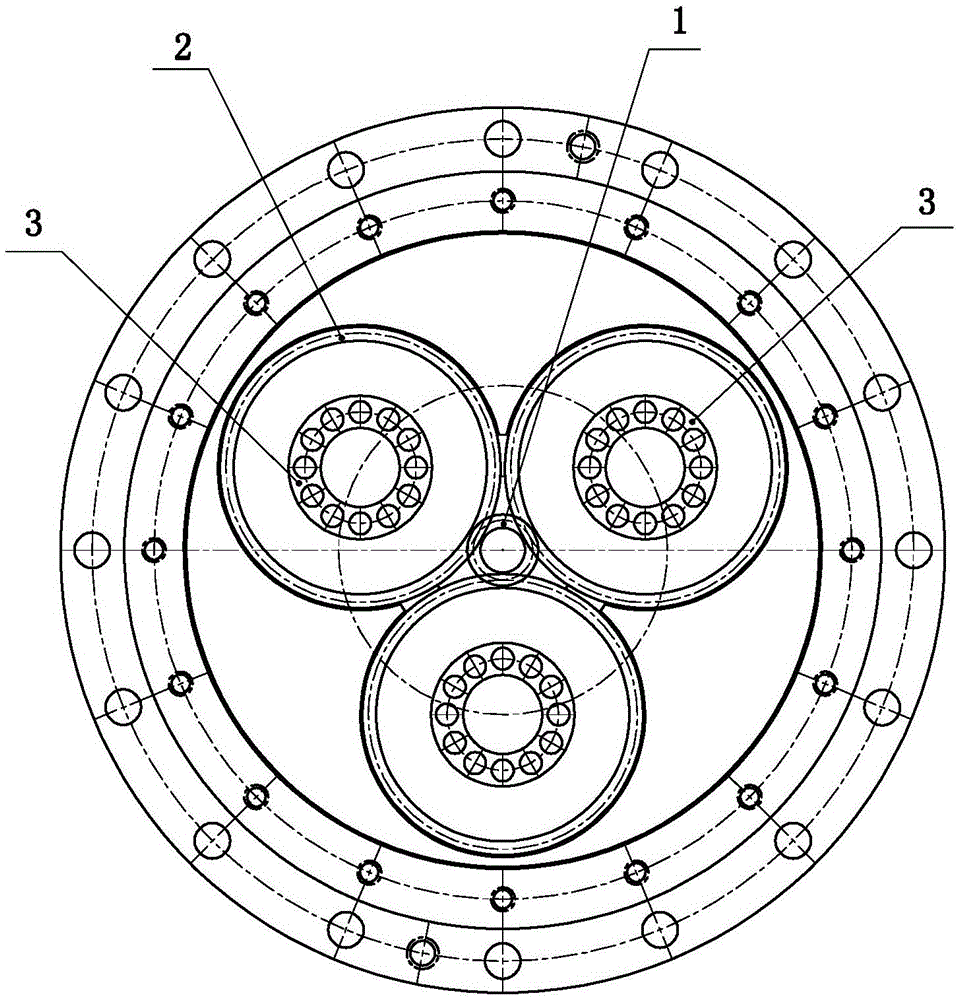
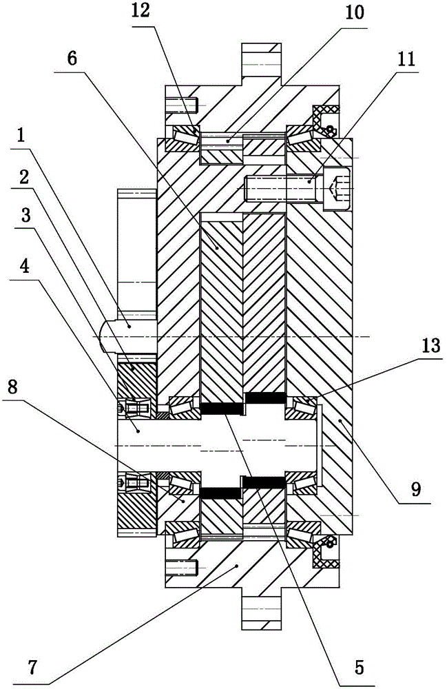
[0017] Such as Figure 1 to Figure 2 As shown, the present invention mainly includes sun gear 1, planetary gear 2, expansion sleeve 3, cycloid shaft 4, cycloid bearing 5, cycloid gear 6, casing 7, front cycloid shaft flange 8, rear cycloid shaft flange 9. Connecting pins 10, screws 11, housing assembly bearings 12 and cycloid shaft positioning bearings 13, the present invention will be described in detail below in conjunction with the accompanying drawings.

[0018] Such as figure 1 , figure 2 As shown, the casing 7 is the main body of the present invention, and the casing is a circular hollow structure as a whole, and an internal ring gear is arranged on the casing. One end of the casing is provided with a front cycloid shaft flange 8, and a sun gear 1 is rotated on the front cycloid shaft flange, and three planetary gears 2 are arranged around the sun gear, and the three planetary gears are evenly distributed on the same circumference . The planetary gear is fixedly ins...


PUM


Abstract

The invention relates to a precise reduction transmission mechanism which has the advantages of favorable properties and high precision. The precise reduction transmission mechanism is characterized by comprising a sun wheel, a planetary wheel, a tensioning sleeve, cycloidal shafts, a cycloidal gear, a shell, a front cycloidal shaft flange and a back cycloidal shaft flange, wherein the front cycloidal shaft flange and back cycloidal shaft flange are fixedly connected and respectively rotatablely installed in the shell; the three cycloidal shafts are rotatablely installed between the front cycloidal shaft flange and back cycloidal shaft flange, and uniformly distributed on one circumference; the cycloidal shaft which protrudes out of the front cycloidal shaft flange is fixedly provided with the planetary wheel; the front cycloidal shaft flange is rotatablely provided with the sun wheel; the sun wheel and planetary wheel form a mesh fit; the cycloidal shaft arranged inside the shell is provided with the cycloidal gear; and a cycloidal bearing is arranged between the cycloidal gear and cycloidal shaft and forms a mesh fit with an inner gear ring positioned on the shell. The reduction mechanism has the advantages of favorable properties and high precision, and is beneficial to popularization and application in industry.

Description

technical field [0001] The invention relates to the technical field of mechanical transmission, in particular to a precision reduction transmission mechanism. Background technique [0002] Many areas of society will involve mechanical deceleration transmission, especially in the field of industrial robot manufacturing, aerospace, military industry, medical equipment, etc. Due to the constraints of space and environment, the requirements for transmission mechanisms are very strict, and the deceleration transmission mechanism is required to be small in size and light in weight. Also, the output torque and the transmission ratio are large and the transmission precision is required to be high. There are several existing transmission mechanisms such as: RV reducer, cycloid reducer, harmonic reducer, etc. Although they have been widely used in the above fields, there are still difficulties in manufacturing and processing, low yield, high cost, and difficulty in mass production. P...

Claims


Application Information

Patent Timeline
Patent Type & Authority Applications(China)
IPC IPC(8): F16H1/32F16H57/021
CPCF16H1/32F16H57/021
Inventor 宋志安
Owner 山东万维传动科技有限公司
Why Eureka
Try Eureka