Dynamic pressure sensor chip

A sensor chip and dynamic pressure technology, applied in the direction of measuring fluid pressure, measuring fluid pressure through electromagnetic components, fluid pressure measurement using optical methods, etc., can solve the problem of large acceleration effect, low working temperature, and aggravated p-n junction leakage, etc. problems, to achieve the effect of ensuring dynamic characteristics, excellent performance and avoiding pollution

Inactive Publication Date: 2015-12-09
NO 49 INST CHINESE ELECTRONICS SCI & TECH GRP
View PDF6 Cites 4 Cited by
  • Summary
  • Abstract
  • Description
  • Claims
  • Application Information

AI Technical Summary

Problems solved by technology

Among them, the piezoelectric type has a high working temperature, the maximum temperature is 260°C, but it is large in size and has a large acceleration effect; the capacitive application circuit is complex, the cost is high, and the generally tolerated working temperature is not high; the silicon piezoresistive type has a small size, Stable performance, anti-vibration and shock, operating temperature range is better than that of electret microphones, etc., but when the temperature exceeds 125°C, the leakage of the p-n junction between the strain resistance and the substrate will increase, and the excitation of this card will cause the p-n junction to fail, etc. Factors make the sensor unable to meet the needs of practical applications
Therefore, the current dynamic pressure sensor has some problems in the measurement field, such as the working temperature does not cover, and the measurement range does not meet the actual needs.

Method used


Image

  • Dynamic pressure sensor chip
  • Dynamic pressure sensor chip
  • Dynamic pressure sensor chip

Examples


specific Embodiment approach 1

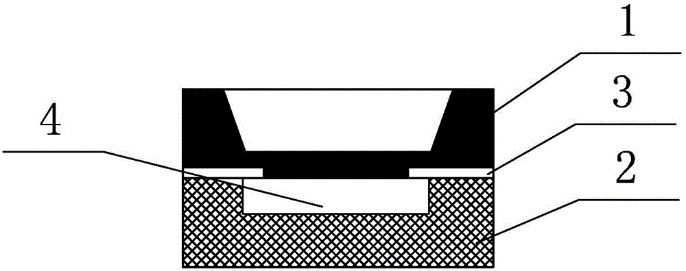
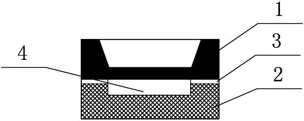
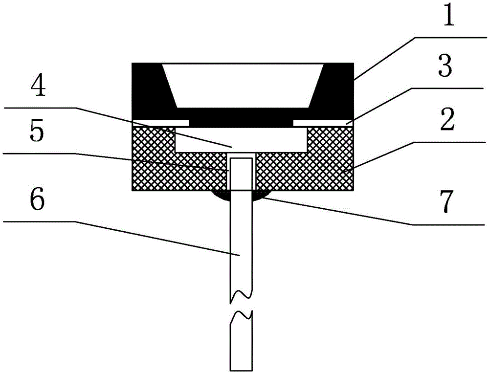
[0016] Specific implementation mode 1. Combination Figure 1 to Figure 8 Illustrate following specific implementation mode, it comprises pressure-sensitive chip 1 and glass substrate 2, and the bonding surface of pressure-sensitive chip 1 is electrostatically sealed and bonded on the bonding surface of glass substrate 2; In pressure-sensitive chip 1 and glass substrate 2, the four sides of the bonding surface of the pressure sensitive chip 1 or the four sides of the bonding surface of the glass substrate 2 are evenly and symmetrically provided with microfluidic channels 3.

specific Embodiment approach 2

[0017] Embodiment 2. The difference between this embodiment and the dynamic pressure sensing chip described in Embodiment 1 is that the material of the pressure sensitive chip 1 is a silicon wafer or a high temperature resistant SOI wafer made by oxygen injection isolation technology.

specific Embodiment approach 3

[0018] Embodiment 3. The difference between this embodiment and the dynamic pressure sensing chip described in Embodiment 1 or 2 is that the pressure sensitive chip 1 adopts a flat membrane or beam membrane piezoresistive structure or a flat membrane with an optical mirror surface. Or corrugated membrane structure.


PUM


Abstract

The invention provides a dynamic pressure sensor chip, and belongs to the technical field of dynamic pressure sensors. The objective of the invention is to manufacture the dynamic pressure sensor chip by adopting a mode of electrostatic bonding of a silicon chip or an SOI chip with fluid porous channels and a glass substrate or adopting the mode of electrostatic bonding of the silicon chip or the SOI chip and the glass substrate with the fluid porous channels so that piezoresistive and optical dynamic pressure signal detection can be realized. The dynamic pressure sensor chip comprises a pressure-sensitive chip (1) and the glass substrate (2). The bonding surface of the pressure-sensitive chip (1) is adhered on the bonding surface of the glass substrate (2) via electrostatic sealing. Micro fluid porous channels (3) are symmetrically and evenly distributed at the sides around the bonding surface of the pressure-sensitive chip (1) or the sides around the bonding surface of the glass substrate (2) at the connecting position of the pressure-sensitive chip (1) and the glass substrate (2). Dynamic pressure signal detection of the piezoresistive principle and the optical principle can be realized by the dynamic pressure sensor chip, and the dynamic pressure sensor chip is suitable for application in the environment of high temperature and strong electromagnetic interference.

Description

technical field [0001] The invention belongs to the technical field of dynamic pressure sensors, and in particular relates to a pressure sensing chip. Background technique [0002] The measurement of dynamic pressure is of great significance for calculating the launch speed of missiles, monitoring the fatigue degree of pressure devices or the amplitude of strong noise, etc. In some applications, dynamic pressure sensors are required to have high temperature resistance, strong electromagnetic resistance, and good dynamic characteristics. There are currently three main types of sensors for dynamic pressure detection: piezoelectric, capacitive and silicon piezoresistive. Among them, the piezoelectric type has a high working temperature, the maximum temperature is 260°C, but it is large in size and has a large acceleration effect; the capacitive application circuit is complex, the cost is high, and the generally tolerated working temperature is not high; the silicon piezoresist...

Claims


Application Information

Patent Timeline
Patent Type & Authority Applications(China)
IPC IPC(8): G01L9/16G01L11/02
Inventor 史鑫王伟吴亚林徐兴烨曹永海王世宁桂永雷
Owner NO 49 INST CHINESE ELECTRONICS SCI & TECH GRP
Why Eureka
Try Eureka