
Multifunctional wireless data transmission seismic wave exploration instrument

A wireless data transmission and seismic wave technology, applied in the direction of seismic signal receivers, etc., can solve the problems of insufficient number of channels, difficult to achieve, and powerlessness, etc., and achieve the effects of low power consumption, easy operation, and light weight

Inactive Publication Date: 2015-12-09
WUHAN ENG SCI & TECH RESINST
View PDF4 Cites 10 Cited by
  • Summary
  • Abstract
  • Description
  • Claims
  • Application Information

AI Technical Summary

Problems solved by technology

In this case, traditional seismographs often fail due to their insufficient channel count
In addition, there is a common problem in petroleum seismic exploration and engineering seismic exploration, that is, usually, people hope to use small source energy to obtain a larger exploration depth, if so, the contribution to both is very huge
However, looking at domestic and foreign seismic prospecting instruments, it is difficult to do this at present, and in actual work, the way to increase the depth of seismic exploration is to increase the amount of explosives at the source and the multiple coverage technology. In other words, engineering seismic exploration is sometimes difficult to do, because in most cases, it is not allowed to use large explosives for seismic exploration work
In addition, for a long time, seismic exploration instruments and shallow seismometers used for oil exploration have been independent of each other. This problem is caused by the fact that the number of channels of traditional seismic instruments is fixed in advance by the manufacturer and cannot be changed.

Method used


Image

  • Multifunctional wireless data transmission seismic wave exploration instrument
  • Multifunctional wireless data transmission seismic wave exploration instrument
  • Multifunctional wireless data transmission seismic wave exploration instrument

Examples


Embodiment Construction

[0020] The present invention will be further described in detail below in conjunction with the accompanying drawings and specific embodiments.

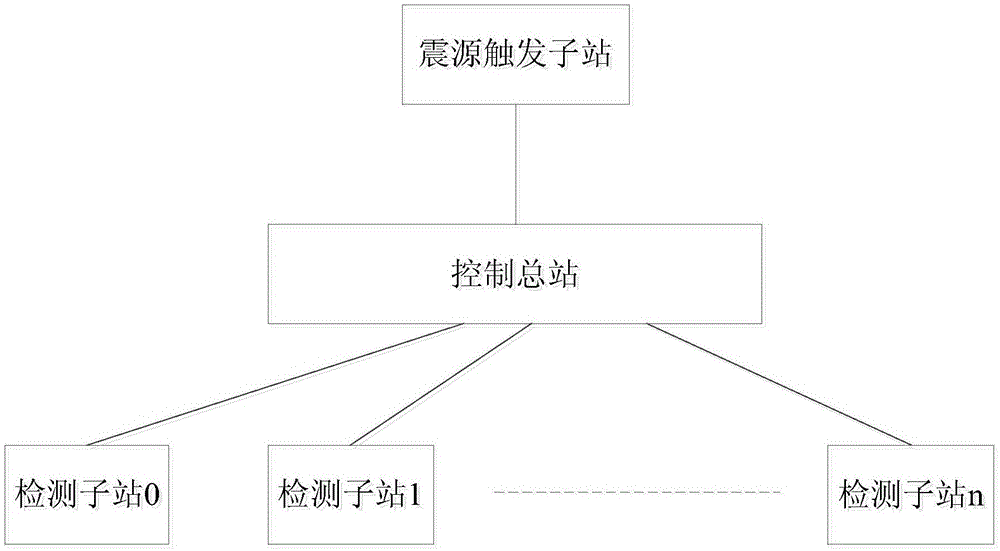
[0021] Such as figure 1 As shown, the multifunctional wireless data transmission seismic wave prospecting instrument of the present invention includes a main control station, a plurality of detection sub-stations, and a seismic source trigger sub-station. in,

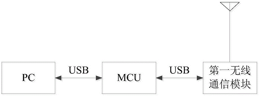
[0022] The structure of the control station is as follows figure 2 Shown, comprise microcomputer (PC, PersonalComputer), embedded microprogram controller MCU (MicroprogrammedControlUnit) and the first wireless communication module, embedded microprogram controller is connected between microcomputer and the first wireless communication module, wherein, embedded microprogrammed control unit The program controller is connected with the microcomputer through the USB interface, and the embedded microprogram controller is connected with the first wireless communication module thro...


PUM


Abstract

The invention relates to a multifunctional wireless data transmission seismic wave exploration instrument, including: a control master station which includes a microcomputer and a first wireless communication module connected with the microcomputer; a plurality of detection substations each of which includes a data acquisition module and a second wireless communication module connected with the data acquisition module, the second wireless communication module of each detection substation being connected with the first wireless communication module through a wireless channel; and a seismic source triggering substation connected with the control master station. The control master station, the plurality of detection substations and the seismic source triggering substation used by the multifunctional wireless data transmission seismic wave exploration instrument are simple in structure and convenient to operate, electronic components that are used have small power and is low in power consumption, and thus no extra storage batteries are needed. The whole seismograph is light in weight and is convenient to carry.

Description

technical field [0001] The invention relates to a seismograph, in particular to a multifunctional wireless data transmission seismic wave prospecting instrument. Background technique [0002] Among the many geophysical prospecting methods, the seismic wave prospecting method has always played a pivotal role. Especially in the fields of petroleum exploration and engineering geophysical prospecting, seismic wave exploration methods are indispensable. As we all know, in the preliminary exploration work of oil resources, seismic exploration is the main exploration method. It is no exaggeration to say that seismic exploration has made great contributions to my country's oil and gas field exploration. Similarly, in a large number of engineering constructions in my country, the seismic wave exploration method is used for the construction of large-scale infrastructure such as urban high-rise buildings, large factory buildings, urban subways, expressways, high-speed railways, bridg...

Claims


Application Information

Patent Timeline
Patent Type & Authority Applications(China)
IPC IPC(8): G01V1/18
Inventor 肖柏勋李太全刘玉金彦叶辉佘建峡周超张佩刘黎
Owner WUHAN ENG SCI & TECH RESINST
Learn More