
Directional broadband efficient surface wave excitation device

An excitation device, surface wave technology

Active Publication Date: 2015-12-09
XIAN INSTITUE OF SPACE RADIO TECH
View PDF1 Cites 1 Cited by
  • Summary
  • Abstract
  • Description
  • Claims
  • Application Information

AI Technical Summary

Problems solved by technology

[3] G.J.Rich, "The Launching of a Plane Surface Wave", Proceedings of the IEE-Part B: Radio and Electronic Engineering, Volume 102, Issue 2, March 1955, PP.237–246.) The horn is used as a directional excitation device, and the horn is only used as an experimental device for narrowband excitation of surface waves in this paper. Analyze the broadband characteristics, since the surface wave is excited by a single aperture fed by a coaxial-waveguide, its excitation bandwidth should be around 2:1 octave
In addition, the excitation device also has the disadvantages of being mechanically coupled with the reactance surface, which is not convenient for flexible application.
In summary, the existing research on surface wave excitation devices is not enough to support the above-mentioned application requirements, and there is a lack of broadband and high-efficiency surface wave excitation devices. The focus of the present invention is to propose a new type of directional broadband high-efficiency surface wave excitation device

Method used


Image

  • Directional broadband efficient surface wave excitation device
  • Directional broadband efficient surface wave excitation device
  • Directional broadband efficient surface wave excitation device

Examples


Embodiment

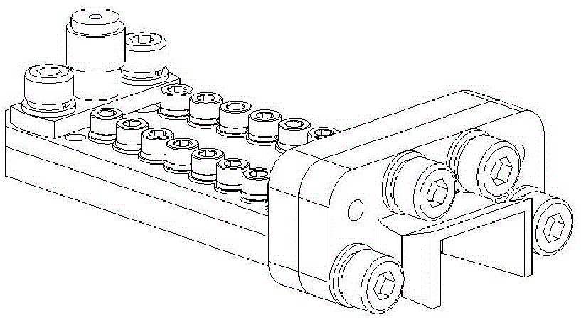
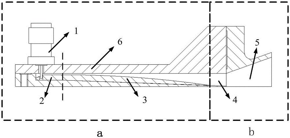
[0045] Such as image 3 and Figure 4 As shown, firstly, the broadband signal fed by the probe is converted into the main mode signal of the ridge waveguide through the coaxial-ridge waveguide conversion, and then further transformed into the main mode signal of the waveguide through the ridge waveguide-waveguide conversion. At the same time, in order to realize the miniaturization of the structure, the ridge waveguide-waveguide conversion is integrated with the downward excitation section, so the conversion directly transitions to the optimal surface wave excitation aperture required by the center frequency. At this time, the guided waves from the central frequency band of the coaxial interface can be converted into surface waves with high efficiency. However, for the upper and lower side frequencies, the excitation aperture is difficult to be optimal. In order to further expand the working bandwidth, an upward opening section is added. This excitation section directly uses t...


PUM


Abstract

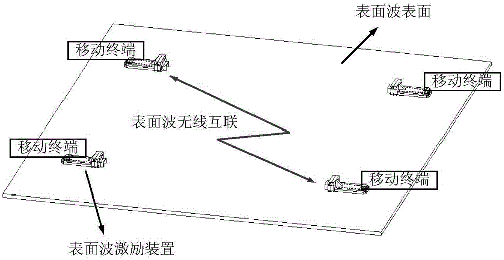
The invention provides a directional broadband efficient surface wave excitation device. The directional broadband efficient surface wave excitation device comprises an input matching section, an excitation section and a cover plate, wherein the input matching section comprises a coaxial connector, a coaxial-ridge waveguide switch and a ridge waveguide-waveguide switch; the excitation section comprises a downwards excitation section and an upwards excitation section. Non-contact between an inner core of the coaxial connector and the single ridge waveguide can be realized by opening a pore on a ridge of the single ridge waveguide. The excitation section adopts a two-stage structure to realize the broadband efficient surface wave excitation. Compared with the existing excitation device, the excitation device provided by the invention obviously improves the bandwidth performance and excitation efficiency, and can flexibly move on the surface of the surface wave and enhance the flexibility of application. The directional broadband efficient surface wave excitation device provided by the invention is wide in frequency band, high in surface wave excitation efficiency, compact in structure, easy in processing and low in cost; a surface wave wireless transmission system is formed by the directional broadband efficient surface wave excitation device and the surface of the surface wave, so that the excitation device can flexibly access and remove from the surface of the surface wave, thus the wireless fast transmission application requirement for high speed big data by the millimeter wave frequency band in the future can be satisfied.

Description

technical field [0001] The invention relates to a directional broadband high-efficiency surface wave excitation device, which belongs to the technical field of high-speed wireless communication and interconnection. Background technique [0002] In 1907, Zenneck derived the solution expression of the surface wave by using the Maxwell equation, and proved the existence of the surface wave theoretically. Zenneck surface wave (referred to as "surface wave") has the following four unique characteristics: [0003] Power saving: Compared with the three-dimensional spherical transmission of space waves, surface waves are transmitted in two-dimensional planes, so the power of surface waves is 1 / r instead of 1 / r 2 The proportional attenuation reduces the power requirement, which is very important in the millimeter wave frequency band; [0004] Good electromagnetic compatibility: The electric field exponentially decays in the vertical surface direction, showing unique non-radiative c...

Claims


Application Information

Patent Timeline
Patent Type & Authority Applications(China)
IPC IPC(8): H03H9/02H03H9/25
Inventor 万继响王旭东汤建辉弓金刚张明涛吴春邦
Owner XIAN INSTITUE OF SPACE RADIO TECH
Learn More