Mixing material conveying device of pneumatic fertilization device

A technology of fertilization device and feeder, which is applied in the direction of spraying device, liquid spraying device, etc., can solve the problems of not having liquid fertilizer spraying function, complex structure, uneven fertilization, etc., and achieve simple structure, high fertilization efficiency, and fertilization uniform effect

Active Publication Date: 2015-12-16
石柱土家族自治县农业特色产业发展中心
View PDF9 Cites 10 Cited by
  • Summary
  • Abstract
  • Description
  • Claims
  • Application Information

AI Technical Summary

Problems solved by technology

[0003] Existing fertilizer spreaders are driven by the power output shaft to rotate the fertilizer spreader to spread the fertilizer by centrifugal force. There are two types of single disc and double disc, which have the disadvantages of complex structure and uneven fertilization. The fertilizer machine can only spread solid particle fertilizer, but does not have the spraying function of liquid fertilizer

Method used


Image

  • Mixing material conveying device of pneumatic fertilization device
  • Mixing material conveying device of pneumatic fertilization device

Examples


Embodiment 1

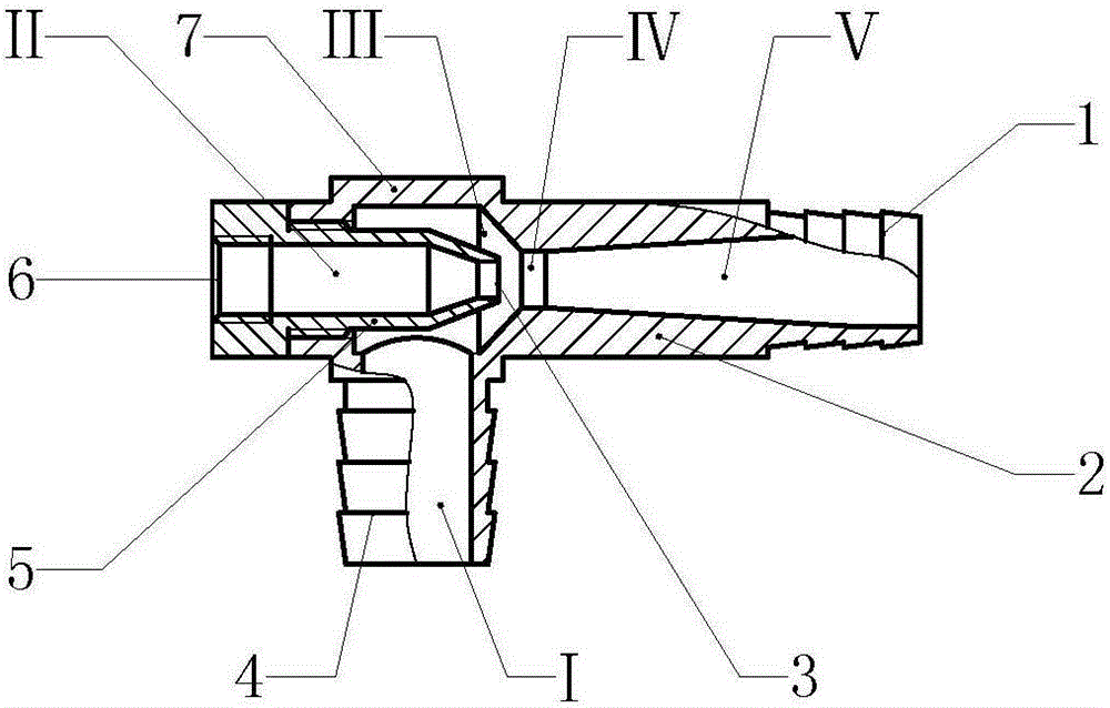
[0013] Example 1 attached figure 1 In the shown embodiment, a mixing feeder of a pneumatic fertilization device is composed of a mixing body 7, a nozzle 2 and a pneumatic nozzle 5, the mixing body 7 and the nozzle 2 are connected as one, and the mixing body 7 is sprayed The rear end of the pipe 2, the mixing body 7 is a hollow structure, and the pneumatic nozzle 5 is placed in the inner space of the mixing body 7 from the rear end of the mixing body 7; the inner space of the pneumatic nozzle 5 constitutes the air passage II, and the air passage The rear end of II has a compressed air input interface 6 connected, and the front part of the pneumatic nozzle 5 has a pneumatic nozzle 3. The front part of the pneumatic nozzle 3 is a hollow conical structure that shrinks from the back to the front. Pneumatic channel II, the diameter of the inner space of the air nozzle 3 gradually shrinks from the back to the front; the back space of the nozzle 2 is a conical structure that shrinks...

Embodiment 2

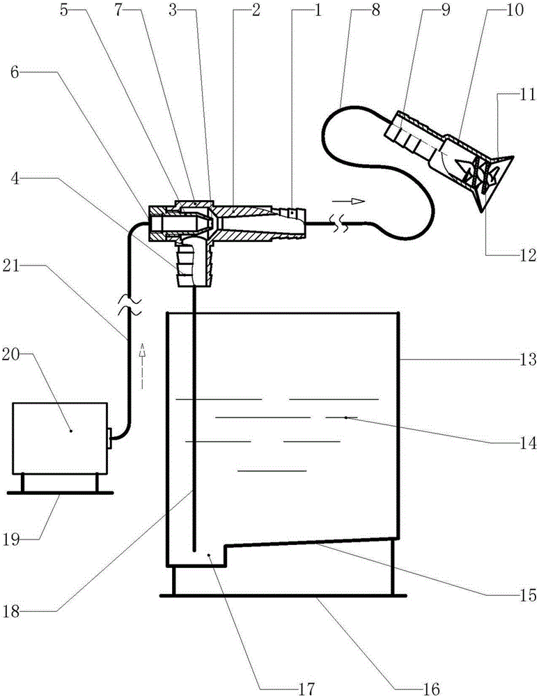
[0015] Example 2 attached figure 2 In the shown embodiment, the mixing feeder of the first embodiment is applied in the pneumatic fertilization device, and the pneumatic fertilization device is composed of an air pump 20, an air delivery pipe 21, a mixing feeder, a suction pipe 18, a feed tank 13, a feeding The pipe 8 and the fertilization nozzle 10 are composed, and the structure of the mixing feeder and the connection mode between the mixing feeder and the peripheral equipment are as described in the first embodiment, and will not be repeated here. Equipped with liquid fertilizer or pesticide in feed pool 13, there is collection pit 17 at the bottom of feed pool 13, and the pool bottom of feed pool 13 is slope-shaped pool bottom, and slope-shaped pool bottom carries out slope towards collection pit 17 direction, and suction pipe 18 The lower end of the lower end stretches into the sump 17, so that the suction pipe 18 can fully absorb the liquid fertilizer or pesticide tha...


PUM


Abstract

The invention relates to a fertilizing tool, in particular to a mixing material conveying device of a pneumatic fertilization device. The mixing material conveying device is composed of a material mixing body, a spraying pipe and a pneumatic sprayer. The material mixing body and the spraying pipe are connected into a whole. The material mixing body is arranged at the rear end of the spraying pipe. The pneumatic sprayer is arranged in the inner space of the material mixing body. A pneumatic channel is formed by the inner space of the pneumatic sprayer. The rear end of the pneumatic channel is connected with a compressed air input connector. A pneumatic nozzle is arranged at the front portion of the pneumatic sprayer. The inner space of the pneumatic nozzle is communicated to the pneumatic channel. The inner space of the rear portion of the spraying pipe is of a conical structure rapidly shrinking. The inner space of the front portion of the spraying pipe is of a conical structure gradually expanding. A jet orifice is formed between the rear portion and the front portion of the spraying pipe. A supercharging material conveying cavity is formed by the conical inner space of the front portion of the spraying pipe. A negative-pressure cavity is formed by the peripheral space of the pneumatic nozzle. Pneumatic fertilization is utilized, a mechanical action mechanism is not needed for the fertilization device, air and fertilizer are sufficiently mixed, fertilization is even, and the fertilization efficiency is high. The mixing material conveying device is suitable for spraying liquid fertilizer or pesticides and is also suitable for spraying solid particle fertilizer.

Description

technical field [0001] The invention relates to an agricultural machine, in particular to a fertilizing implement. Background technique [0002] Fertilizer is a kind of substance that provides essential nutrients for crops, improves soil properties, and improves soil fertility. When the soil cannot provide the nutrients needed for crop growth, fertilization must be carried out. [0003] Existing fertilizer spreaders are driven by the power output shaft to rotate the fertilizer spreader to spread the fertilizer by centrifugal force. There are two types of single disc and double disc, which have the disadvantages of complex structure and uneven fertilization. The fertilizer machine can only spread the fertilizer of solid particles, and does not have the function of spraying liquid fertilizer. Contents of the invention [0004] The purpose of the present invention is to overcome the shortcomings of the existing fertilization equipment, to provide a mixing feeder used in the ...

Claims


Application Information

Patent Timeline
Patent Type & Authority Applications(China)
IPC IPC(8): B05B9/04B05B15/06
Inventor 吴水仙
Owner 石柱土家族自治县农业特色产业发展中心
Why Eureka
Try Eureka