Eureka AIR delivers breakthrough ideas for toughest innovation challenges, trusted by R&D personnel around the world.

Improved protection door of intelligent numerical control lathe

A technology for CNC lathes and protective doors, which is used in turning equipment, maintenance and safety accessories, time registers, etc., and can solve problems such as the uncertainty of hidden safety hazards of protective doors, complicated correspondence between keys and locks, and long outage intervals. , to achieve the effect of prolonging the effective working time, eliminating the unlocking and matching process, and improving safety and reliability.

Active Publication Date: 2015-12-16
ZHEJIANG JINTANG MACHINE TOOL
View PDF9 Cites 2 Cited by
  • Summary
  • Abstract
  • Description
  • Claims
  • Application Information

AI Technical Summary

Problems solved by technology

[0002] CNC lathes are the most important processing equipment in the field of industrial device processing, especially in the field of precision and complex parts processing. During the processing of parts, CNC lathes have a relatively complex processing environment such as flying debris of castings. The cooling and temperature adjustment of the lathe are difficult to achieve. At the same time, relying solely on the cooling liquid to cool the processing equipment after processing has problems such as long outage intervals, low efficiency, incomplete cooling, and difficulty in controlling and recycling the coolant splash. Furthermore, CNC The complex working environment of the lathe itself also determines that the management and control of CNC machine tools is risky and difficult, and it is difficult to coordinate and plan. It cannot form an efficient and unified management model and requires a large amount of manpower.
[0003] Due to the complex processing environment of CNC lathes and high processing precision requirements in the existing technology, it is difficult to properly control the temperature and ventilation of the CNC lathe during processing, and at the same time, it is impossible to realize the combination of cooling liquid and cooling fluid for a period of time after the processing is completed. Rapidly reduce the temperature of the processing space, so that the CNC lathe needs to wait for the coolant to be sprayed and the CNC lathe operating equipment, especially the relatively stable CNC lathe drill bit and clamping device with a relatively high temperature, to open the protective door for further ventilation and cooling during the processing interval. This leads to disadvantages such as long intervals and the need to consume certain human resources for intervals. At the same time, conventional ventilation facilities also have problems such as difficulty in maintaining the relative independence of the working environment in the CNC lathe and the external environment, and inability to adapt to the splash of casting debris and coolant; However, the conventional manual opening of the protective door has great potential safety hazards and uncertainties, and is prone to accidents and losses. At the same time, it is difficult for the management personnel of CNC lathes to make a unified overall plan for the management of CNC lathes, and it is impossible to realize authorized personnel in a reasonable place. Under reasonable time and other conditions, the CNC lathes that need to be inspected and ventilated are managed and tested, and the implementation and implementation of the corresponding management work cannot be counted and filed; at the same time, although the lock setting of the CNC lathe can strengthen the security of the CNC lathe and is more suitable for management, but the corresponding relationship between keys and locks is complicated, which causes great inconvenience to use and management, increases the burden of management work, and brings huge troubles to daily maintenance and management when it is accidentally lost or damaged, resulting in waiting The equipment and facilities for management and maintenance cannot be operated before the corresponding keys and locks are replaced, which seriously reduces work efficiency

Method used


Image

  • Improved protection door of intelligent numerical control lathe
  • Improved protection door of intelligent numerical control lathe

Examples


Embodiment Construction

[0017] The specific embodiments of the present invention will be described in detail below with reference to the accompanying drawings.

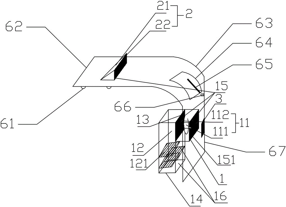
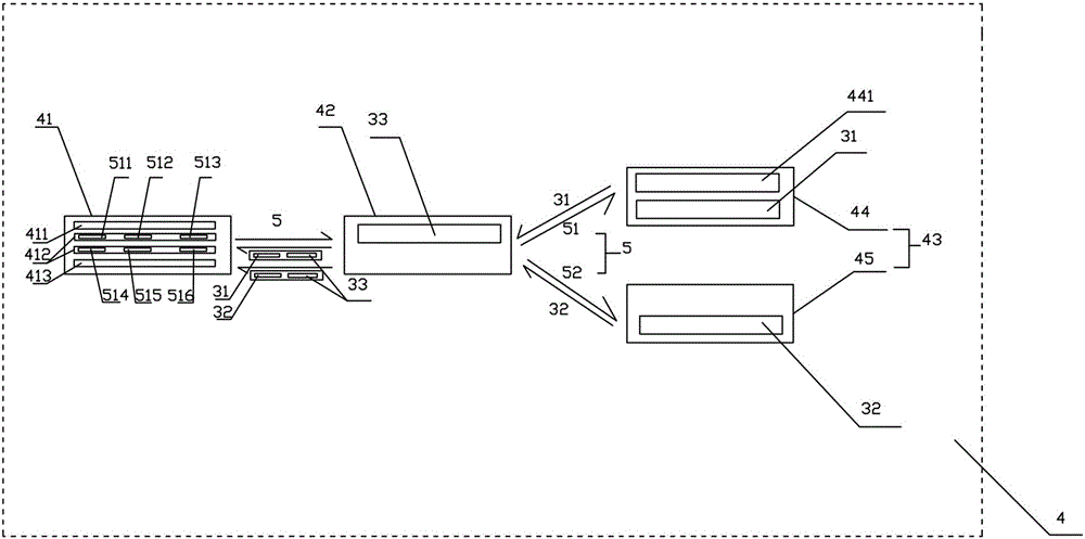
[0018] Such as figure 1 with figure 2 Shown here is an improved protective door for intelligent CNC lathes of the present invention, which includes a horizontal plate 62, a vertical plate 67 and an inclined plate 63. The protective door is arranged on the CNC machine tool and is slidably connected with the protective plate through a sliding groove and a sliding rail. The inner side of the top cover of the protective door is provided with a group of lighting lamps 61, and a window 64 is opened on the protective door. The horizontal plate 62 and the vertical plate 67 are connected by an inclined plate 63. The inclined plate 63 In the shape of an arc, the window 64 is opened on a sloping plate, a curved glass is provided on the window 64, a scraper 65 is provided on the inner side of the curved glass, and one end of the scraper 65 is bent And ex...


PUM


Abstract

The invention relates to an improved protection door of an intelligent numerical control lathe. The improved protection door comprises a draught fan bin, a ventilation bin, a door lock and a mobile terminal control system. The draught fan bin comprises a fan layer and a channel layer. The fan layer comprises a fan and a drive motor driving the fan to rotate forward and reversely, and baffles are arranged in the channel layer. The mobile terminal control system generates and stores operation instructions to control and manage the unlocking of the door lock the forward and reverse rotation of the drive motor. By means of the protection door, the inner environment and the outer environment are isolated, and under the situation that the work of the numerical control lathe is not affected, the working environment of the numerical control lathe is cooled and ventilated so as to stabilize the working environment and prolong the effective work time of the numerical control lathe; meanwhile, the influence on the work of the fan from scraps, cooling liquid and the outer environment can be well prevented, and inner impurities and outer impurities can be removed; and automatic locking and unlocking of the lock, automatic starting and stopping of the drive motor and standard management of the lock and the drive motor are achieved through the design of the operation instructions of the mobile terminal control system, and high expandability is achieved.

Description

Technical field [0001] The invention relates to a protective door for a numerical control lathe, and more specifically to an improved protective door for an intelligent numerical control lathe. Background technique [0002] CNC lathes are the most important processing equipment in the field of industrial device processing, especially the processing of precision and complex parts. In the process of processing parts, CNC lathes have more complex processing environments such as casting debris flying randomly. This processing environment makes the process CNC The cooling and temperature adjustment of the lathe is difficult to achieve. At the same time, the cooling of the processing equipment by the cooling liquid after the processing is completed has problems such as long shutdown intervals, low efficiency, incomplete cooling, and difficulty in controlling and recovering cooling liquid splash. The complex working environment of the lathe itself also determines that the management and...

Claims


Application Information

Patent Timeline
IPC IPC(8): B23Q11/08B23Q11/12B23B25/00G07C9/00
CPCB23B25/00B23Q11/0891B23Q11/12G07C9/00571G07C9/00817G07C9/00896
Inventor 陈戌连丁晓伟
Owner ZHEJIANG JINTANG MACHINE TOOL
Why Eureka
Eureka Blog
Learn More