
Sludge oil removal system and method

An oil system and sludge technology, applied in the field of sludge oil removal system, can solve the problems of high one-time cost and operating cost, few successful examples of industrialization, difficult selection and regeneration of extracting liquid, etc., so as to improve the oil removal effect, Enhance oil removal effect and reduce oil content

Inactive Publication Date: 2015-12-16
WISDRI ENG & RES INC LTD
View PDF6 Cites 4 Cited by
  • Summary
  • Abstract
  • Description
  • Claims
  • Application Information

AI Technical Summary

Problems solved by technology

However, the above-mentioned treatment methods all have high costs and are prone to secondary pollution during the treatment process.
If the incineration method is used to treat oily sewage, a special incinerator needs to be built, and fuel consumption is required, and the one-time cost and operating cost are relatively high; the extraction method needs to undergo multiple extractions to meet the discharge standard, and the selection and regeneration of the extraction liquid are difficult. At present, there are not many successful examples of industrialization; low-temperature pyrolysis in the pyrolysis method can process light waste oil, but it also needs to build a special heating furnace and consume energy, and the cost is high; the solidification method requires a large area of ​​land as a landfill. Leakage will cause secondary pollution

Method used


Image

  • Sludge oil removal system and method
  • Sludge oil removal system and method
  • Sludge oil removal system and method

Examples


Embodiment Construction

[0026] In order to better understand the present invention, the present invention will be further described below in conjunction with the accompanying drawings and specific embodiments.

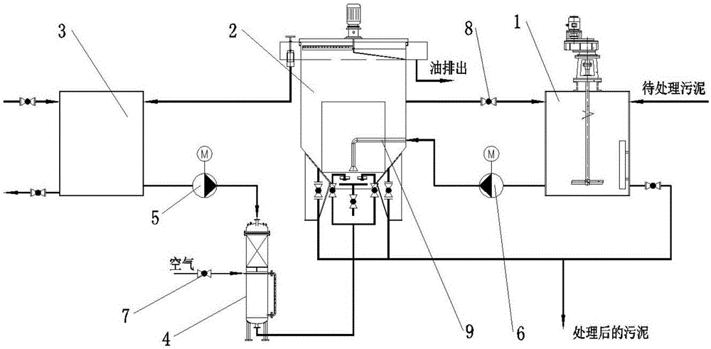
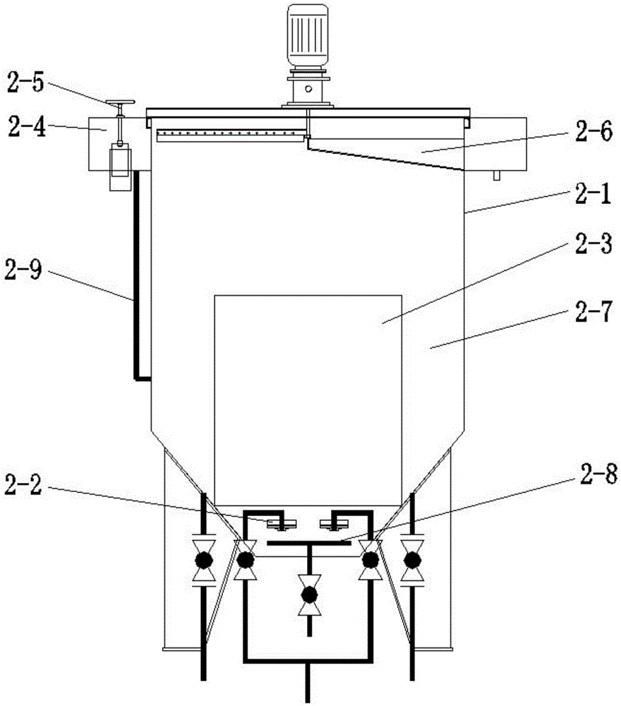
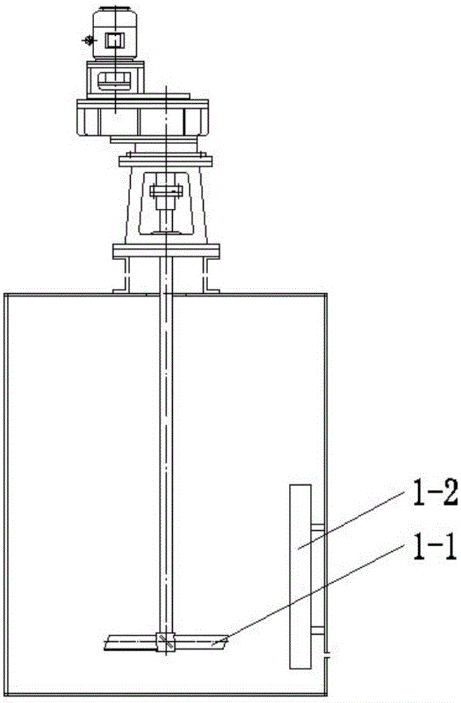
[0027] Such as figure 1 A sludge degreasing system shown includes a stirring device 1, a reaction device 2, an intermediate water tank 3 and an air-dissolving tank 4. The top of the stirring device 1 is provided with a mud inlet, and the bottom is provided with a sewage outlet; The lower part communicates with the bottom of the reaction device 2 through the first connecting pipe 9 (the mud outlet of the first connecting pipe 9 is located at the bottom of the reaction device 2), and the stirred sludge passes through the first connecting pipe 9 (the first connecting pipe 9 is also That is, the feed pipe of the reaction device) leads to the lower part of the reaction device 2, and the first connecting pipe 9 is provided with a sludge lifting pump 6; the top of the reaction device 2 is provided w...


PUM


Abstract

The invention discloses a sludge oil removal system. The sludge oil removal system comprises a stirring device, a reaction device, a middle water tank and a dissolved gas tank, wherein a sludge inlet is formed in the top of the stirring device, and a sludge discharging opening is formed in the bottom of the stirring device; the lower part of the stirring device is communicated with the bottom of the reaction device by virtue of a first communication pipe, the reaction device is communicated with the top of the middle water tank, the bottom of the middle water tank is communicated with the top of the dissolved gas tank, the bottom of the dissolved gas tank is communicated with a gas floatation releaser which is arranged on the inner bottom of the reaction device, and the gas floatation releaser is arranged below a sludge outlet of the communication pipe; an oil discharging opening is formed in the top of the reaction device, and a sludge discharging opening is formed in the bottom of the reaction device. The invention also discloses a sludge oil removal method. Oil is removed by virtue of dissolved gas floatation, partial sludge in the reaction device enters the stirring device so as to further remove the oil, the oil content in the sludge is further reduced, and the oil removal effect is greatly improved; meanwhile, the utilization rate of a charged chemical reagent is increased; partial gas floatation water backflows to the middle water tank to be recycled, so that the water consumption is greatly reduced.

Description

technical field [0001] The invention relates to the technical field of oil removal, in particular to a sludge oil removal system and method. Background technique [0002] A large part of oily sludge (slurry) produced in industrial production is hazardous waste. Oily sludge refers to the mixing of crude oil or refined oil into sludge or other substances. The oil in oily sludge is difficult to recover, which will cause environmental pollution; oily sludge usually contains benzene series, phenols and other substances, accompanied by stench and certain toxicity, and direct discharge without treatment will cause soil, water and vegetation heavily polluted. [0003] At present, the common sludge recovery and utilization treatment methods mainly include physical and chemical treatment methods such as incineration, extraction, pyrolysis and solidification. However, the above-mentioned treatment methods all have problems such as high cost and easy generation of secondary pollution...

Claims


Application Information

Patent Timeline
Patent Type & Authority Applications(China)
IPC IPC(8): C02F11/00C02F101/32
Inventor 张同泉朱少华肖敏杨威马晟
Owner WISDRI ENG & RES INC LTD
Learn More