
High-air-pressure quick-percussion down-the-hole percussive drill tool

A technology of percussion drilling and high air pressure, which is applied in drilling equipment, earthwork drilling, and driving devices for drilling in boreholes. It can solve the problems of complex processing technology, slow drilling speed, and low impact frequency of valveless impactors. Achieve the effect of simple and convenient disassembly of the drill bit, simple structure and improved service life

Active Publication Date: 2015-12-16
HUNAN XINJINGANG MACHINERY EQUIP
View PDF8 Cites 8 Cited by
  • Summary
  • Abstract
  • Description
  • Claims
  • Application Information

AI Technical Summary

Problems solved by technology

[0003] The existing pneumatic down-the-hole impactors in our country are limited by the wind pressure provided by the air compressor (below 1.9Mpa) or continue to use the low-pressure down-the-hole drilling rigs and drilling tools imported from abroad in the past, such as figure 1 In addition, the processing technology of the main parts (such as piston and inner cylinder) of the valveless impactor at that time was complicated, and there was a big gap between the material and heat treatment process and foreign countries; For impactors with low impact frequency (below 20 times / second), the use of materials is not demanding; with the rapid development of my country's modern industry, the production of high-performance air compressors with high wind pressure (above 3.5Mpa), my country's existing The use of the impactor often has problems such as hammer breakage, low drilling speed and jamming of the impactor during use, which can no longer meet the needs of modern industrial production.

Method used


Image

  • High-air-pressure quick-percussion down-the-hole percussive drill tool
  • High-air-pressure quick-percussion down-the-hole percussive drill tool
  • High-air-pressure quick-percussion down-the-hole percussive drill tool

Examples


Embodiment Construction

[0040] In order to enable those skilled in the art to better understand the technical solution of the present invention, the present invention will be described in detail below in conjunction with the accompanying drawings. The description in this part is only exemplary and explanatory, and should not have any limiting effect on the protection scope of the present invention. .

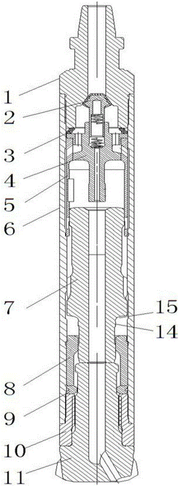
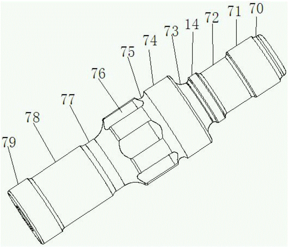
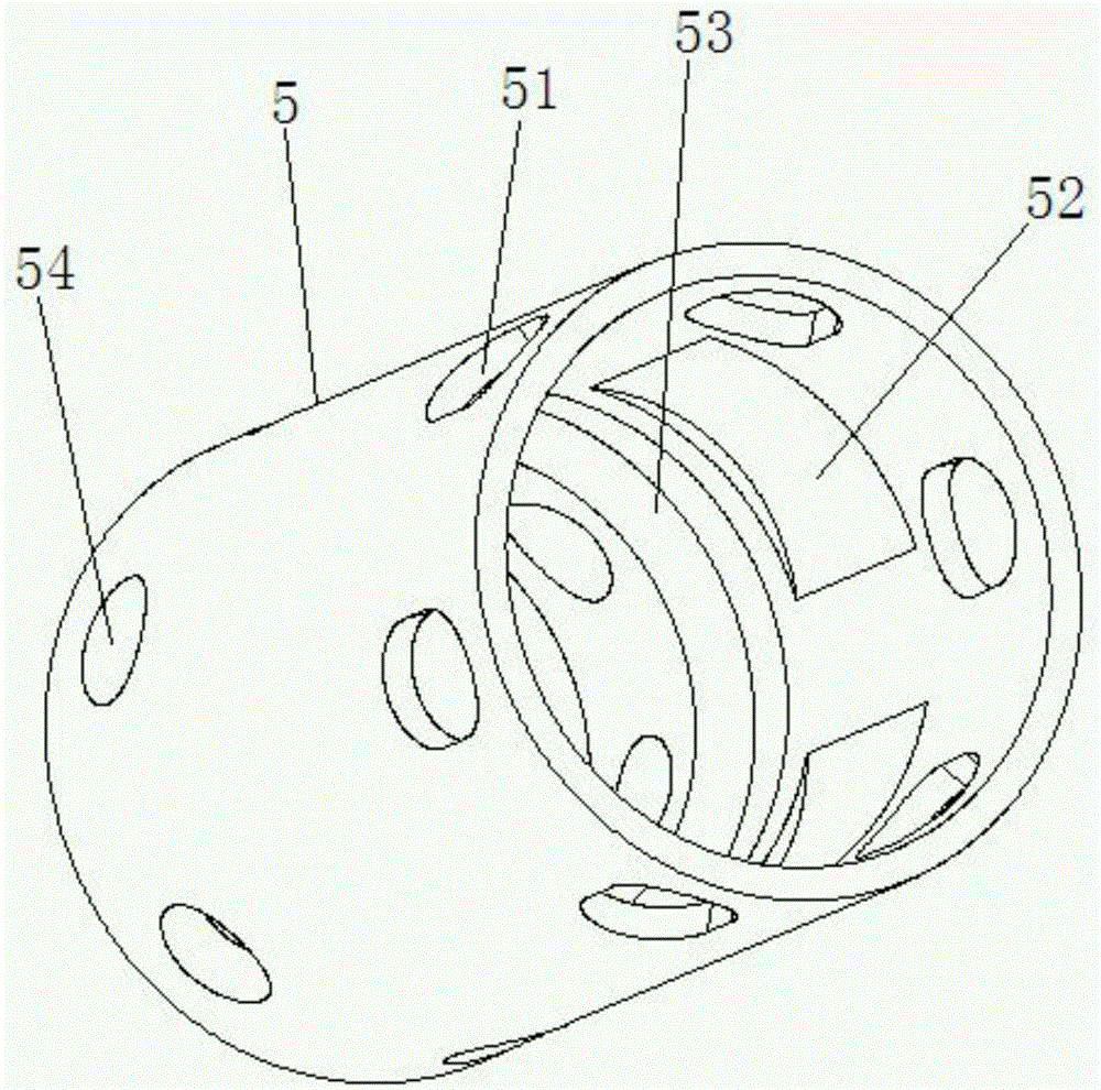
[0041] Such as Figure 1-8 As shown, the connection relationship of the overall structure of the present invention is: a kind of high-pressure fast punching down-the-hole percussion drilling tool, which includes an outer cylinder 6 and a front joint 10 and a rear joint 1 connected to its front and rear ends by threads; the outer cylinder 6 There is a piston 7 socketed with an inner cylinder 5 and a bushing 8; the other end of the inner cylinder 5 is socketed with an air distribution seat 4; a check valve 2 is provided between the air distribution seat 4 and the rear joint 1; The front joint 10 is sock...


PUM


Abstract

The invention discloses a high-air-pressure quick-percussion down-the-hole percussive drill tool. A spring washer is arranged between an air distributor and a rear joint; a snap ring is arranged between a front joint and a bush; a piston is provided with a piston large end; one end of the piston large end is provided with a piston small path; the other end of the piston large end is provided with a piston tail path; one section of the piston large end is a smooth cylinder; the other section of the piston large end is uniformly provided with air grooves; an annular ventilating groove is formed between the air grooves and the smooth cylinder; an annular lug boss is arranged at a position, which is close to the piston large end, of the piston small path; the annular lug boss, the piston large end, an outer cylinder and the bush form a buffering air cavity; the piston tail path is connected with a cylindrical end; a piston tail end is arranged at the tail end of the cylindrical end; front air holes are uniformly formed in one end of an inner cylinder; tail oblique air holes are uniformly formed in the other end of the inner cylinder; arc grooves are uniformly formed in the inner wall of the inner cylinder; and a compressed air chamber is formed between the arc grooves and the tail oblique air holes. The high-air-pressure quick-percussion down-the-hole percussive drill tool is high in drilling speed, not easy to jam, low in failure rate and low in energy consumption; work efficiency is improved greatly; and energy and cost are saved.

Description

technical field [0001] The invention belongs to the technical field of impactor manufacturing, and in particular relates to a high-pressure quick-flushing down-the-hole impact drilling tool. Background technique [0002] Pneumatic down-the-hole impactor, also known as pneumatic down-the-hole hammer, is a pneumatic mechanical drilling tool that uses compressed air as power to push the hammer (piston) to hit the drill bit to form a hole in the gravel; the impactor and the drill bit are in the rock drilling process In the drill pipe connection, it dives into the hole to break the rock at the same time, and the working efficiency is not affected by the hole depth; hence the name of the down-the-hole hammer. Pneumatic down-the-hole hammer drilling technology is widely used in blast hole construction, hydrological well drilling, geological core exploration, reservoir dam foundation curtain grouting, engineering geological exploration, trenchless pipeline laying, building foundatio...

Claims


Application Information

Patent Timeline
IPC IPC(8): E21B4/06
Inventor 杨日权谢伟才
Owner HUNAN XINJINGANG MACHINERY EQUIP
Learn More