Decorative tail pipe for automobile exhaust pipe

A technology for decorating tailpipes and automobile exhaust. It is applied in the direction of exhaust devices, power devices, and noise reduction devices. It can solve problems such as high cost, abnormal vibration, and unsightly appearance, and achieve reasonable structural design, stable mechanical strength, and Avoid the effect of abnormal noise

Inactive Publication Date: 2015-12-16
BAOLONG ANHUI AUTO PARTS
View PDF6 Cites 3 Cited by
  • Summary
  • Abstract
  • Description
  • Claims
  • Application Information

AI Technical Summary

Problems solved by technology

[0003] At present, there are mainly three ways to connect the outlet ends of the inner and outer layers of the decorative tailpipe of automobiles: the first one, the way that the inner and outer layers do not touch, this structure is not easy to ensure uniformity due to the surrounding gaps, and the appearance is not beautiful; the second one, the inner layer is flared, Full welding with the outer layer has the disadvantages of time-consuming welding, grinding and polishing, and high cost. At the same time, it is only suitable for cylindrical tailpipes that are easy to fit; the third type is that the inner layer is inserted into the beading of the outer layer, and the insertion part is partially welded 2- Section 4, due to the welding section, the decorative tailpipe has unsightly appearance defects. If it is not welded, due to the influence of the dimensional accuracy of the sheet metal parts, the inner and outer layers cannot be matched precisely, which is prone to vibration and abnormal noise. The customer is not satisfied with the structural design

Method used


Image

  • Decorative tail pipe for automobile exhaust pipe
  • Decorative tail pipe for automobile exhaust pipe

Examples


Embodiment Construction

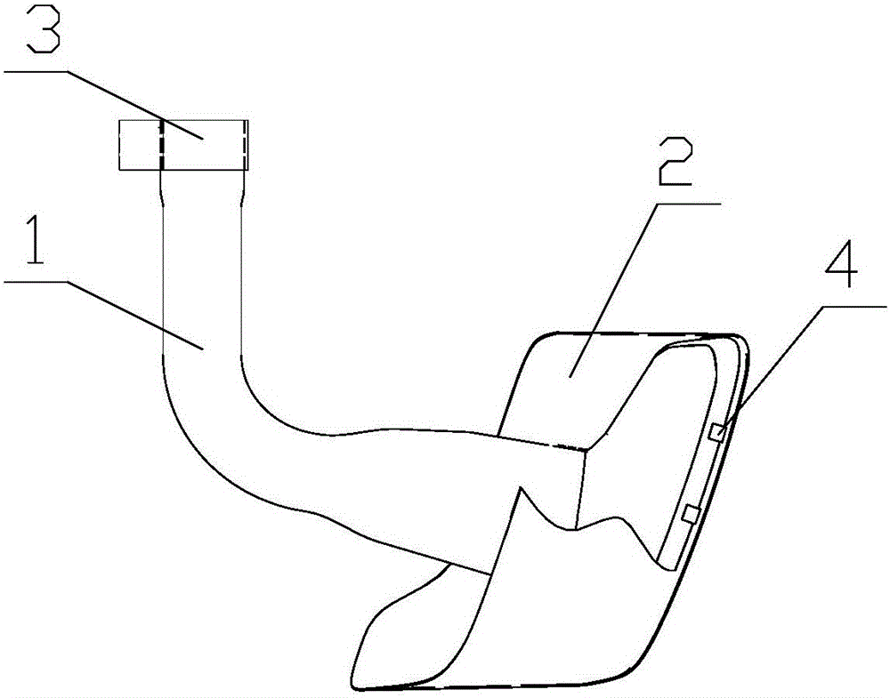
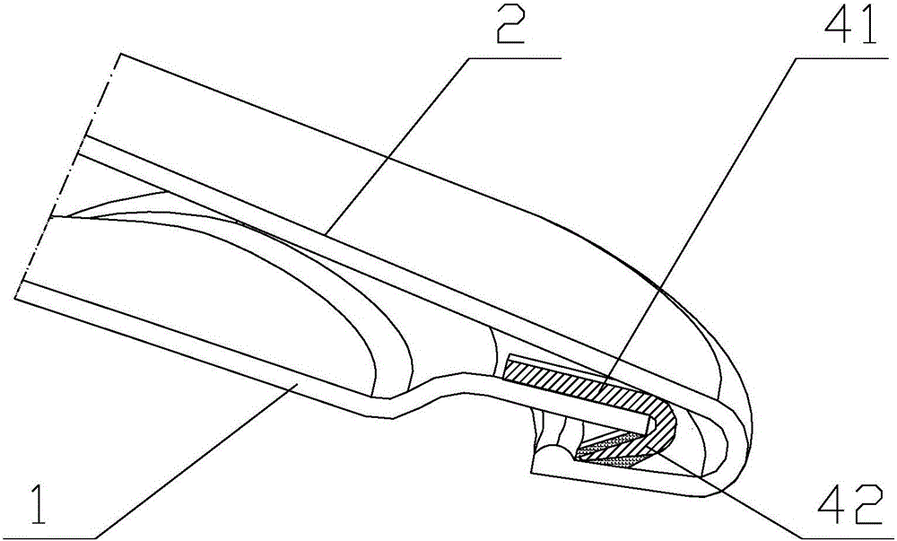
[0020] like figure 1 and 2 as shown, figure 1 It is a structural schematic diagram of a decorative tailpipe of an automobile exhaust pipe proposed by the present invention, figure 2 for figure 1 Schematic diagram of the partial enlarged structure of the decorative tailpipe of the automobile exhaust pipe.

[0021] refer to figure 1 and 2 , a kind of decorative tailpipe of automobile exhaust pipe that the present invention proposes, comprises: inner pipe 1 and outer pipe 2;

[0022] The inner tube 1 includes a first tube part and a second tube part connected in sequence. The end of the first tube part far away from the second tube part is provided with a clamp 3 outside, and the end of the second tube part away from the first tube part is gradually increased in the direction of the radial opening of the tube. Large, the end of the second pipe part away from the opening of the first pipe part is provided with a clamping part, and the outer periphery of the clamping part is...


PUM


Abstract

The invention discloses a decorative tail pipe for an automobile exhaust pipe. The decorative tail pipe comprises an inner pipe and an outer sleeve, one end of the inner pipe is provided with a clamping part, the periphery of the clamping part is provided with a plurality of spring clamping pieces, the shape of the inner wall of the outer sleeve is matched with the inner pipe, one end of the outer sleeve is provided with an edge folding part which is bent towards the inside of an opening, and a clamping groove is formed between the edge folding part and the inner wall of the outer sleeve. One end of the clamping part of the inner pipe can be inserted into the outer sleeve from the opening at one end of the outer sleeve far away from the edge folding part, so that the clamping part is located in the clamping groove and fixedly clamped to the clamping groove through the spring clamping pieces. The decorative tail pipe for the automobile exhaust pipe is simple in process and rational in structural design. By arranging the spring clamping pieces, the inner pipe is fixedly clamped to the outer sleeve, the visual surface of the tail pipe is free of weld joint, and the mechanical strength of the tail pipe is stable. Due to the spring clamping pieces, the inner pipe is in close fit with the outer sleeve, and abnormal sounds generated between the inner pipe and the outer sleeve due to vibration in vehicle running can be effectively avoided.

Description

technical field [0001] The invention relates to the technical field of automobile exhaust, in particular to a decorative tailpipe of an automobile exhaust pipe. Background technique [0002] The function of the tail pipe of the exhaust system is to guide the exhaust gas produced by the engine into the atmosphere. According to the structure, it can be divided into single-layer and double-layer structure, and the single-layer tailpipe is not beautiful enough. The double-layer tail pipe can not only export the exhaust gas, but also provide a beautiful shape for the whole vehicle. [0003] At present, there are mainly three ways to connect the outlet ends of the inner and outer layers of the decorative tailpipe of automobiles: the first one, the way that the inner and outer layers do not touch, this structure is not easy to ensure uniformity due to the surrounding gaps, and the appearance is not beautiful; the second one, the inner layer is flared, Full welding with the outer ...

Claims


Application Information

Patent Timeline
Patent Type & Authority Applications(China)
IPC IPC(8): F01N13/08B60K13/04
CPCB60K13/04F01N13/082
Inventor 熊宜谋杨建军付鹏刘世模张玉楼罗昊
Owner BAOLONG ANHUI AUTO PARTS
Why Eureka
Try Eureka