Optical flow computation method using time domain visual sensor

A technology of visual sensor and calculation method, applied in the field of optical flow calculation, which can solve problems such as inappropriate natural video images, high response delay, and object shape distortion under the assumption of constant brightness, so as to reduce redundant information and output data volume, and reduce calculation Time and resource requirements, the effect of improving real-time performance

Inactive Publication Date: 2015-12-16
TIANJIN NORMAL UNIVERSITY
View PDF3 Cites 27 Cited by
  • Summary
  • Abstract
  • Description
  • Claims
  • Application Information

AI Technical Summary

Problems solved by technology

[0023] (1) The brightness constant assumption is inappropriate for most natural video images, especially when there are occlusions in the image or the motion speed is high;
[0024] (2) When the image is occluded, the velocity field will change suddenly, and various smooth constraints will distort the shape of the object;
[0025] (3) The premise of differential optical flow is that the image is continuous and differentiable. If the image space gradient changes greatly, it will have a serious impact on the accuracy of optical flow analysis
[0035] (2) High response delay
This high response delay is very unfavorable for the tracking and identification of high-speed moving targets. The faster the moving speed, the more obvious the discontinuity and error of the detection results;

Method used


Image

  • Optical flow computation method using time domain visual sensor
  • Optical flow computation method using time domain visual sensor
  • Optical flow computation method using time domain visual sensor

Examples


Embodiment 1

[0082] The present invention uses the TVS differential optical flow calculation method: based on the local smooth assumption proposed by Lucas-Kanade, the AE sequence output by the TVS is used to complete the calculation of the spatial gradient and the temporal gradient.

[0083] spatial gradient

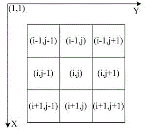
[0084] Ix and Iy are the spatial gradient (change) of brightness at the pixel point (x, y). In the frame-based image method, the brightness difference between a pixel point (x, y) and its surrounding neighbor pixels is used to represent the change of light intensity. The present invention calculates the spatial gradient by using the difference between the accumulated AE numbers of each pixel and its neighbor pixels in the past period of time Δt . Considering the detection line width, TVS noise characteristics and real-time calculation characteristics, the spatial gradient calculation formula is:

[0085]

[0086] In the above formula, AE (x, y, t) represents the AE generated...


PUM


Abstract

The present invention discloses an optical flow computation method using a time domain visual sensor, and specific implementation steps are given out. Different from a current method for performing optical flow computation by adopting "a frame sequence image (video)", the method disclosed by the present invention uses a visual information acquisition device-time domain visual sensor to perform optical flow computation of a field of view. Furthermore, because each pixel autonomously performs change detection and asynchronous output, motion and change of an object in a scenario can be sensed in real time, a continuity assumption of "no change in brightness and no change in local speed" in a differential optical flow computation method is well satisfied, and the real-time property of optical flow computation is greatly improved while the precision of optical flow computation is significantly improved. Therefore, the method is very suitable for optical flow computation and subsequent tracking and speed measurement of the high-speed moving object.

Description

technical field [0001] The invention relates to multiple technical fields such as computer vision, image processing, and image sensor design, and more specifically relates to a method for calculating optical flow using a time-domain vision sensor. Background technique [0002] light flow [0003] Optical flow (Opticflow, also known as image flow) refers to the motion projection generated when a moving target in three-dimensional space is imaged on a two-dimensional image plane. It is called optical flow. The purpose of studying the optical flow field is to approximate the motion field in three-dimensional space which cannot be directly obtained from sequence images. [0004] Optical flow analysis is one of the important research directions of video analysis. With the help of optical flow analysis, moving target detection, tracking and segmentation can be effectively performed. Optical flow analysis has been widely used in many fields such as robotics, military, aerospa...

Claims


Application Information

Patent Timeline
Patent Type & Authority Applications(China)
IPC IPC(8): G06T17/00
Inventor 胡燕翔
Owner TIANJIN NORMAL UNIVERSITY
Why Eureka
Try Eureka