
Power storage device, method for producing same, and device for producing same

A technology for electric storage equipment and manufacturing devices, which is applied in the directions of packaging capacitor devices, terminal application devices, and final product manufacturing, and can solve the problems of film capacitor operation efficiency reduction, change, and tediousness, etc.

Inactive Publication Date: 2015-12-16
KOJIMA PRESS IND CO LTD
View PDF7 Cites 2 Cited by
  • Summary
  • Abstract
  • Description
  • Claims
  • Application Information

AI Technical Summary

Problems solved by technology

Therefore, when the type (capacitance) of the target film capacitor is changed, it is necessary to perform cumbersome work: changing the setting of the number of laminated metallized films in the film capacitor element manufacturing device, and also changing necessary equipment and operating conditions accordingly
In addition, this may lead to a problem that the work efficiency of manufacturing film capacitors may decrease.
Furthermore, there is also a disadvantage that new equipment is required when a film capacitor having a larger electrostatic capacitance to the extent that it is difficult to manufacture with existing equipment is required
[0009] In addition, for conventional film capacitors, when a dielectric breakdown occurs inside the film capacitor element, although a layer of dielectric film that has produced the above-mentioned dielectric breakdown can gradually perform a self-recovery function, there is no way to prevent the breakdown. The means to carry out in the thickness direction of the film capacitor element (the lamination direction of the dielectric film and the metal deposition film)
[0010] In addition, in electricity storage devices other than thin film capacitors that use basic cells (having a structure formed by laminating at least one electricity storage film and a multilayer internal electrode film alternately), for example, lithium, magnesium, calcium, iron, zinc In all solid-state secondary batteries, air secondary batteries, etc., which are used as positive electrode active materials or negative electrode active materials, or as electrodes, there are also problems similar to those of the above-mentioned film capacitors.

Method used

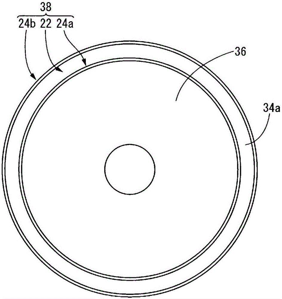
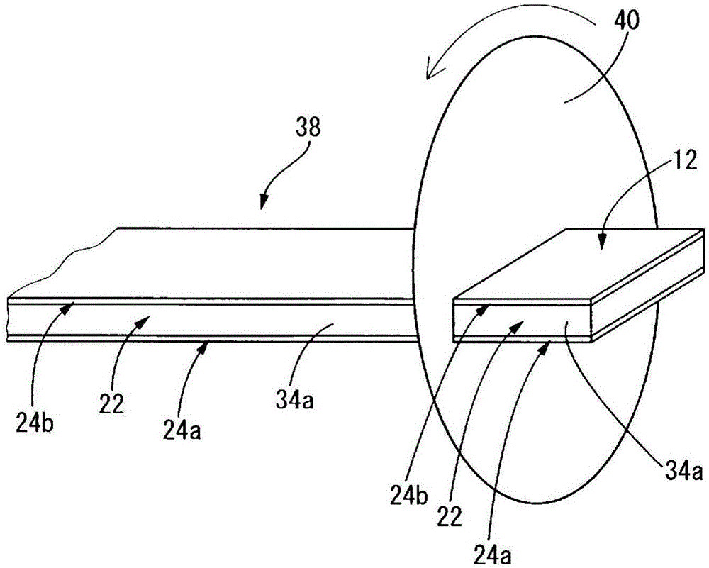

Image

  • Power storage device, method for producing same, and device for producing same
  • Power storage device, method for producing same, and device for producing same
  • Power storage device, method for producing same, and device for producing same

Examples


Embodiment Construction

[0081] Hereinafter, in order to describe the present invention more concretely, embodiments of the present invention will be described in detail with reference to the drawings.

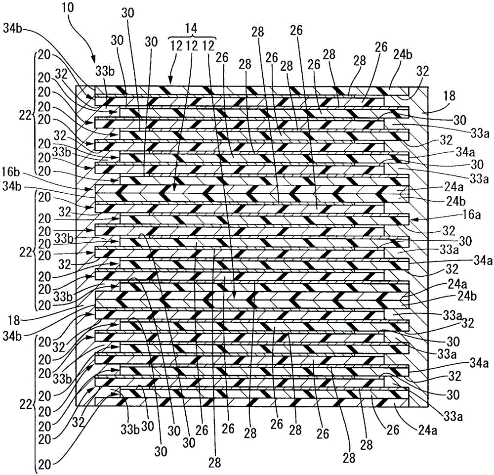
[0082] first, figure 1 A vertical cross-sectional form of a film capacitor which is an embodiment of an electrical storage device having the structure of the present invention is shown in . by the above figure 1 It can be seen that the film capacitor 10 of the present embodiment has three film capacitor elements 12 as electricity storage elements. Furthermore, the structure is as follows: These three thin film capacitor elements 12, 12, 12 are stacked on each other to form a laminated body 14, and on two side surfaces 16a, 16b corresponding to each other in the direction perpendicular to the stacking direction of the laminated body 14, the three film capacitor elements 12, 12, 12 are formed respectively. Metallized electrodes 18 as external electrodes.

[0083] More specifically, the thin film capa...


PUM


Abstract

Provided is a power storage device which is improved so as to make it possible to advantageously prevent the progression of breakdown in the thickness direction thereof, and can be efficiently produced in a plurality of types having different capacities. The power storage device is configured by: stacking a plurality of power storage elements (12) provided with a structure obtained by additionally layering electrically insulating protective films (24a, 24b) on the end surfaces on both sides of a substrate unit (22) obtained by alternatingly layering one or more power-storage films (26) and a plurality of inner electrode films (28); and forming external electrodes (18, 18) on each of the lateral surfaces (16a, 16b) of the layered body (14) comprising the plurality of power-storage elements (12) so as to straddle the respective lateral surfaces (34a, 34a, 34b, 34b) of adjacent power-storage elements (12, 12).

Description

technical field [0001] The present invention relates to an electrical storage device, a manufacturing method thereof, and a manufacturing device thereof, and a film capacitor, a manufacturing method thereof, and a manufacturing device thereof, and more particularly relates to a basic unit (having at least one electrical storage body film and a multilayer internal electrode film formed by alternately stacking) Structure) of a multilayer electrical storage device and a film capacitor, and a method and apparatus for advantageously manufacturing the above-mentioned multilayer electrical storage device and film capacitor. Background technique [0002] Conventionally, power storage devices such as capacitors and secondary batteries have been used in various electronic devices and electric devices. Furthermore, in recent years, along with the increasing demand for downsizing of electronic equipment and electric equipment, downsizing of the structure of electric storage equipment is...

Claims


Application Information

Patent Timeline
Patent Type & Authority Applications(China)
IPC IPC(8): H01G4/18H01G4/30
CPCH01G4/30H01G4/385H01G4/232H01G4/18H01G13/003H01G13/006H01G4/008Y02P70/50H01G4/005H01G4/012H01G4/02H01G4/306
Inventor 小岛洋一郎末次健介
Owner KOJIMA PRESS IND CO LTD
Learn More