Cutting tool of blender

A technology for mixers and knives, applied in the field of mixer knives, can solve the problems of blade fracture, mixer knives wear, affecting mixing work, etc., and achieve the effects of increasing mixing intensity, increasing overall thickness, and improving material effect.

Active Publication Date: 2015-12-23
HUIYANG ALLAN PLASTIC & ELECTRIC INDS
View PDF5 Cites 7 Cited by
  • Summary
  • Abstract
  • Description
  • Claims
  • Application Information

AI Technical Summary

Problems solved by technology

Blades on blender knives pose a safety hazard to cut users
[0003] During the mixing process, due to the presence of hard substances in the material, the knives of the mixer will be severely worn after long-term use, and even the blades will be broken, which will affect the mixing work and increase the cost of replacing new blades
In addition, the blades of the above two blades are bent upwards or downwards at a certain angle relative to the plane where the wing root is located to improve the mixing and cutting effect on materials. However, since the blades and the horizontal plane are at a certain angle, the When mixing hard materials, the balance of the tool is poor, the mixing and cutting effect on the material is not good, and the tool generates a lot of noise when stirring
Moreover, in order to ensure that the knife blade of the blade is bent at a predetermined angle, the complexity of the knife manufacturing process is increased, and the production quality of the knife is difficult to guarantee
[0004] The current mixer blade also has a structure in which each blade and wing root are on the same level, but the structure of this blade is relatively simple, and the mixing and crushing effect is poor.

Method used


Image

  • Cutting tool of blender
  • Cutting tool of blender
  • Cutting tool of blender

Examples


Embodiment 1

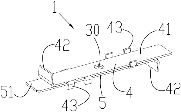
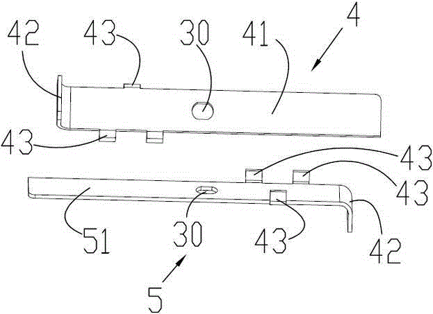
[0033] Such as Figure 1 to Figure 3 As shown, the blade 1 of the blender knife includes two sub-blades, namely a first sub-blade 4 and a second sub-blade 5 . The first sub-blade 4 includes a first cutter body 41 . The second sub-blade includes a second cutter body 51 . Both the first cutter body 41 and the second cutter body 51 are flat. Furthermore, both the first blade body 41 and the second blade body 51 are formed in a straight shape. Because the cutter bodies of the first sub-blade 4 and the second sub-blade 5 are flat, that is, the two cutter bodies are parallel to each other, and the two cutter bodies are parallel to the horizontal plane, there is no included angle, so the mixer cutter is in the working process It can effectively ensure the balance of the blade. Even if a hard object is stirred, the mixer knife is not easy to lose balance, so that the noise generated by the mixer knife during work can be effectively reduced.

[0034] The material is stirred and pu...

Embodiment 2

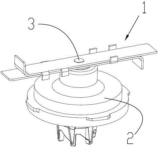
[0041] Such as Figure 4 As shown, the structure of the blender cutter in this embodiment is basically the same as that in Embodiment 1, the main difference between the two lies in the connection between the first sub-blade 4 and the second sub-blade 5 . In Embodiment 1, the first sub-blade 4 and the second sub-blade 5 are two independent blades respectively, and they are fixedly connected to the tool seat 2 through the connecting shaft 3 in the manner of stacking up and down. However, in Embodiment 2, the first sub-blade 4 and the second sub-blade 5 are integrally formed. The first sub-blade 4 and the second sub-blade 5 can be processed into an integrated blade by using precision casting technology, or sintering technology, or CNC machine tool processing technology, or 3D printing technology. The specific structure of the first sub-blade and the second sub-blade is the same as that of Embodiment 1, and will not be repeated here. Making the first sub-blade 4 and the second s...

Embodiment 3

[0044] Such as Figure 5 As shown, the structure of the blender cutter in this embodiment is basically the same as that in Embodiment 1, and the main difference between the two is that the two sub-blades are provided with blades. In Example 1, neither the first sub-blade nor the second sub-blade is provided with blades, and the material is stirred and pulverized mainly through the collision between the two sub-blades and multiple blades and the material. However, in Embodiment 3, both the first sub-blade 4 and the second sub-blade 5 are provided with cutting edges. In this embodiment, the first sub-blade 4 and the second sub-blade 5 are still centrally symmetrical about the center of the connecting hole, so as to ensure that the mixer blade can effectively maintain a balance during high-speed rotation. Therefore, only the specific structure of the first sub-blade is described here, and the structure of the second sub-blade is not described in detail.

[0045] At least one en...


PUM


Abstract

The invention relates to a cutting tool of a blender. The cutting tool comprises a blade, a tool holder and a connecting shaft. The blade is fixed onto the tool holder through the connecting shaft and comprises at least two auxiliary blades, each auxiliary blade comprises a flat blade body, and the auxiliary blades are in attached connection in a pairwise vertically coincided manner. The cutting tool of the blender has the advantages of ingenious structure, high stirring strength, low noise and high balance degree.

Description

technical field [0001] The invention relates to the technical field of mixers, in particular to a mixer cutter. Background technique [0002] The mixer cutter undertakes the task of cutting and mixing during the mixing process. Existing mixer knives are roughly divided into two types, one is a cross-shaped blade, which includes a wing root and four blades connected to the wing root, and each blade is bent upward or downward relative to the plane of the wing root , a blade for cutting materials is provided on each blade; the other is a straight blade, including a wing root and two blades connected to the wing root, and blades are provided on the two blades. The blades on the blender knives present a safety hazard for cutting the user. [0003] During the mixing process, due to the presence of relatively hard substances in the material, the knives of the mixer will be severely worn after long-term use, and even the blades will be fractured, which will affect the mixing work ...

Claims


Application Information

Patent Timeline
Patent Type & Authority Applications(China)
IPC IPC(8): A47J43/07A47J43/046
CPCA47J43/0722B01F27/0725B01F27/172B01F27/808
Inventor 张树生
Owner HUIYANG ALLAN PLASTIC & ELECTRIC INDS
Why Eureka
Try Eureka