
Hybrid power multi-shaft rotor wing unmanned aerial vehicle

A rotary-wing unmanned and hybrid technology, applied in the field of unmanned aerial vehicles, can solve the problems such as the inability of the oil and electric power to back up each other, the complex structure, the uncontrolled fall of the aircraft, etc., so as to improve the safety of the whole machine, good safety, and long flight time. Effect

Inactive Publication Date: 2015-12-23
BEIJING HONGWAN WEIPENG INFORMATION TECH
View PDF4 Cites 20 Cited by
  • Summary
  • Abstract
  • Description
  • Claims
  • Application Information

AI Technical Summary

Problems solved by technology

The fuel engine has a high energy density, but the torque-variable transmission mechanism uses mechanical transmission components such as gears and belts. The structure is complex, the failure rate is high, and the flight control algorithm is single. Any problem with one axis will cause the entire aircraft to fall out of control
[0005] c) Using one fuel engine + mechanical torque variable transmission mechanism + propeller series assembly and multiple lithium batteries + electric motor + electronic governor + propeller series assembly in parallel as a multi-axis oil-electric hybrid system, using the fuel engine to provide the main lift, The electric motor provides pitching, rolling and other attitude control force and auxiliary lift, but the degree of freedom of fuel-powered attitude control is limited, it cannot fly independently, and the oil-electric power cannot be backed up by each other, and it needs to manually pull the rope to start the oil engine to take off, reliability and practicability needs improvement

Method used


Image

  • Hybrid power multi-shaft rotor wing unmanned aerial vehicle
  • Hybrid power multi-shaft rotor wing unmanned aerial vehicle
  • Hybrid power multi-shaft rotor wing unmanned aerial vehicle

Examples


Embodiment Construction

[0019] The present invention will be further described below in conjunction with the accompanying drawings.

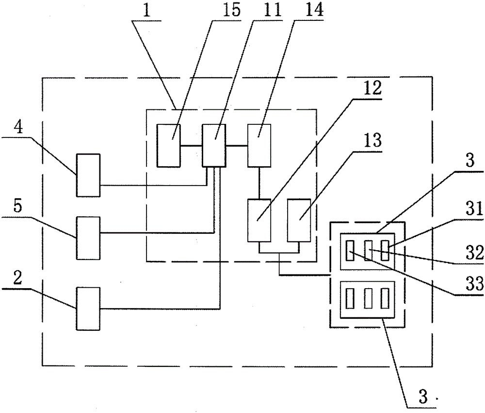
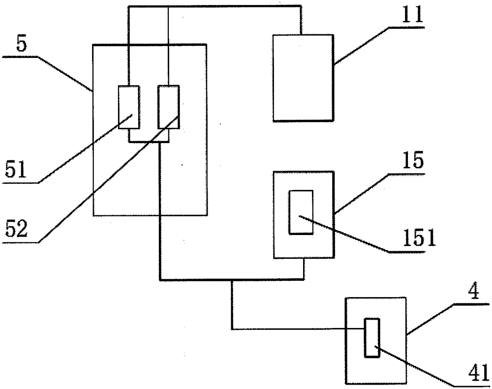
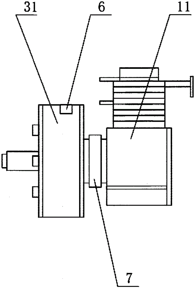
[0020] Such as figure 1 As shown, a hybrid multi-axis rotor UAV described in the present invention includes a UAV body, and the UAV body includes a flight control system 2 and a multi-axis drive system arranged in the casing. It also includes a fuel-electric hybrid system 1, a servo module 5 and a measurement and control module 4; the fuel-electric hybrid system 1 is composed of a fuel piston engine 11, a fuel tank 15, a power generation module 14, a rectification module 12 and a lithium battery 13; the fuel piston One end of the engine 11 is connected to the fuel tank 15 through an oil pipe, the other end of the fuel piston engine 11 is connected to the servo module 4, the output shaft of the fuel piston engine 11 is connected to the power generation module 14, and the power generation module 14 is connected to one end of the rectification module 12. The rectification...


PUM


Abstract

The invention relates to the technical field of unmanned aerial vehicles, in particular to a hybrid power multi-shaft rotor wing unmanned aerial vehicle. The hybrid power multi-shaft rotor wing unmanned aerial vehicle comprises an unmanned aerial vehicle body. The unmanned aerial vehicle body comprises a flight control system and a multi-shaft drive system arranged inside a vehicle shell. The hybrid power multi-shaft rotor wing unmanned aerial vehicle is characterized by further comprising an oil-electricity hybrid power system, a servo module and a measurement and control module; the oil-electricity hybrid power system is composed of an oil-fired piston engine, an oil tank, an electricity generation module, a rectifier module and a lithium battery; one end of the oil-fired piston engine is connected with the oil tank through an oil pipe; the other end of the oil-fired piston engine is connected with the servo module; an output shaft of the oil-fired piston engine is connected with the electricity generation module; the electricity generation module is connected with one end of the rectifier module; the other end of the rectifier module is connected with the lithium battery in parallel and then is connected with the multi-shaft drive system; the multi-shaft drive system is composed of a plurality of single-shaft drivers. The hybrid power multi-shaft rotor wing unmanned aerial vehicle has the advantages of being long in endurance, large in load, easy to control, good in safety and the like.

Description

technical field [0001] The invention relates to the technical field of unmanned aerial vehicles, in particular to a hybrid multi-axis rotor unmanned aerial vehicle. Background technique [0002] With the development of science and technology, drones are also widely used in military and civilian fields. Existing multi-axis rotor UAVs have three power modes: [0003] a) Multiple lithium batteries + electric motors + electronic governor + propeller series components are used in parallel as a multi-axis electric power system, which is currently the power mode used by most multi-axis rotor drones, with fast flight control response and high power density However, due to the low energy density of lithium batteries, no matter how the body loses weight, the flight time of electric multi-axis rotor drones mostly does not exceed tens of minutes. [0004] b) Using multiple fuel engines + mechanical torque converters + propeller series components connected in parallel as a multi-axis o...

Claims


Application Information

Patent Timeline
IPC IPC(8): B64D27/08B64D27/24
CPCY02T50/60
Inventor 张延伟
Owner BEIJING HONGWAN WEIPENG INFORMATION TECH
Learn More