
A kind of tunnel sealing facility and sealing method thereof

A tunnel and crushed stone technology is applied in the field of blocking flood discharge facilities in non-coal mine tailings ponds, which can solve the problems of polluting the surrounding environment, easily causing harm, polluting the water source, etc., and achieves economical and reasonable construction. Effect

Active Publication Date: 2018-01-19
金建工程设计有限公司
View PDF5 Cites 0 Cited by
  • Summary
  • Abstract
  • Description
  • Claims
  • Application Information

AI Technical Summary

Problems solved by technology

Mine tunnel sealing can only refer to the relevant tunnel design specifications of the water conservancy department at present. At present, the tunnel sealing adopts concrete structure sealing. Once the concrete structure sealing is completed, the head difference it resists is fixed. The difference in water head (water depth) is too large, exceeding the design requirements, causing both water leakage and sand leakage, which is very easy to cause harm (leakage of tailings in the reservoir will pollute the surrounding environment, and may flood a large area of ​​farmland or pollute water sources)
Even if it is blocked at the initial end of the flood drainage system (at the location of the drainage well), the plugging will easily fail due to the heightening of the tailings pond or the impact of the earthquake

Method used


Image

  • A kind of tunnel sealing facility and sealing method thereof
  • A kind of tunnel sealing facility and sealing method thereof
  • A kind of tunnel sealing facility and sealing method thereof

Examples


Embodiment Construction

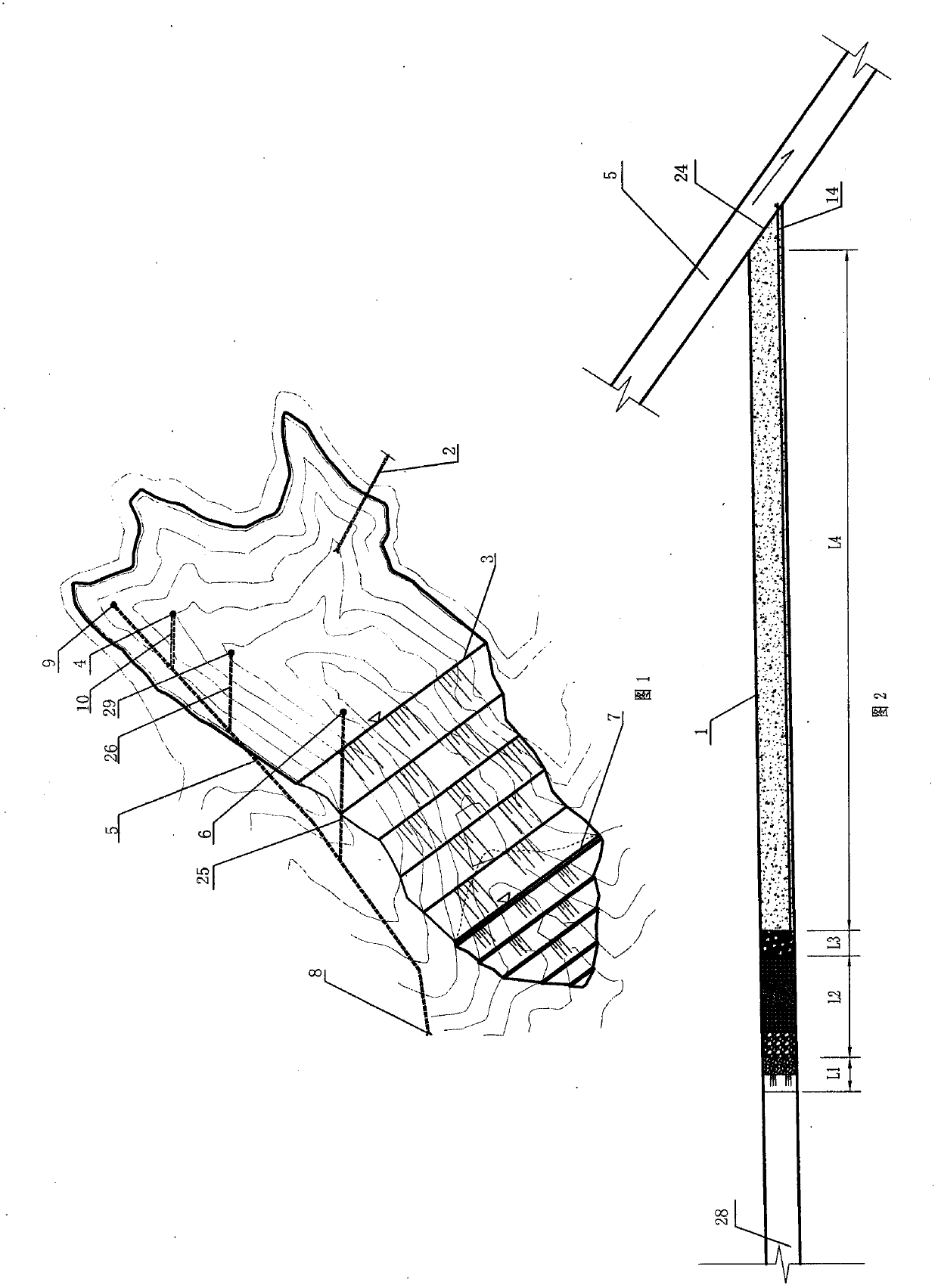
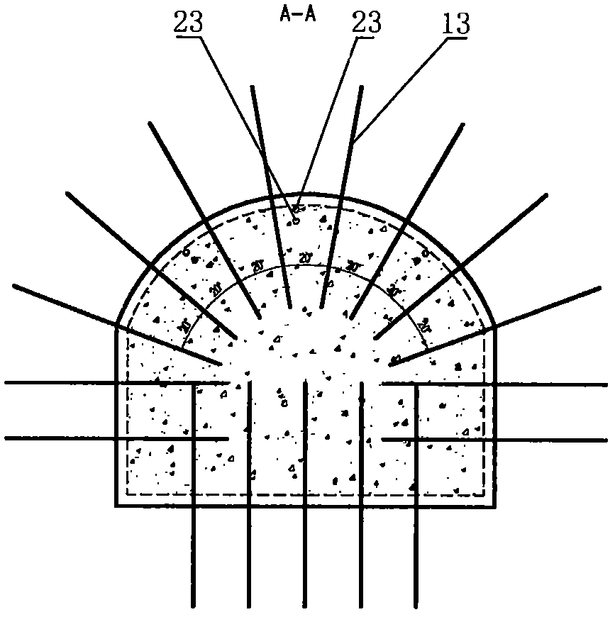
[0033] Such as Figures 2 to 10 As shown, a tunnel sealing facility of the present invention includes a blocking tunnel 1, one end of the blocking tunnel 1 is connected with the drainage tunnel 5, the other end of the blocking tunnel 1 is connected with the tailings pond, and the blocking tunnel 1 is provided with a protective body 27. Filtering body, water collecting body and blocking body 22, protection body 27 is located on the left side of the filtering body, filtering body is located on the left side of the water collecting body, water collecting body is located on the left side of the blocking body 22, and the blocking body 22 is adjacent to the drainage tunnel 5 side, the protective body 36 is adjacent to the side of the tailings pond, the sealing body 22 is provided with a drainage pipe 14, the drainage pipe 14 runs through the sealing body 22, one end of the drainage pipe 14 is connected with the water collection body, and the other end of the drainage pipe 14 It comm...


PUM


Abstract

The invention discloses a tunnel plugging facility and a tunnel plugging method. The tunnel plugging facility comprises a plugging tunnel, a water draining tunnel and a tailing pond, wherein one end of the plugging tunnel is communicated with the water draining tunnel; the other end of the plugging tunnel is communicated with the tailing pond; the plugging tunnel is provided with a protective body, a water filtering body, a water collecting body and a plugging body; the water collecting body is positioned on the left side of the plugging body; the plugging body is adjacent to one side of the water draining tunnel; the protective body is adjacent to one side of the tailing pond; the plugging body is provided with a water draining pipe; the water draining pipe penetrates through the plugging body; one end of the water draining pipe is communicated with the water collecting body; the other end of the water draining pipe is communicated with the water draining tunnel. The tunnel plugging method comprises the following steps: roughening a plugging section, sweeping the plugging section, plugging the tunnel, constructing the water collecting body, constructing the protective body and the water filtering body, and completing the protective body. According to the invention, dead weight of tailings and water of the tailing pond is utilized to dewater tailings in the tailing pond, so that tailings in the tunnel gradually solidifies, the water permeability is reduced, length of the seeping-pipe in front of the plugging body is shortened, the tunnel can be effectively plugged, and mill tailings are stopped.

Description

technical field [0001] The invention relates to a tunnel sealing facility and a sealing method thereof, in particular to a mine tailing pond tunnel sealing facility and a sealing method thereof, and belongs to the technical field of flood discharge facility closure of non-coal mine tailing ponds. Background technique [0002] At present, tailings stockpiling methods include wet, dry and semi-dry in between. The tailings of most ore concentrators adopt traditional wet treatment, that is, the tailings are directly transported to the tailings pond in the form of slurry for storage, and the concentration of the tailings slurry is not more than 60%; the dry storage method that emerged in the 1980s, dry storage The stockpiling method is to process the tailings slurry into a tailings filter cake after pressure filtration, and then stack it. The concentration of the tailings filter cake is about 80%. In the late 1990s, combining the advantages and disadvantages of wet discharge and...

Claims


Application Information

Patent Timeline
Patent Type & Authority Patents(China)
IPC IPC(8): E21F17/00
CPCE21F17/00
Inventor 唐文超王敬瑞贾晔张强强李瑞林李永进袁立业马吉祥呼艳芬郝维兵王德强史彦海陈欢田永辉
Owner 金建工程设计有限公司
Learn More