
Air-floatation supporting device for actively regulating and controlling air pressure of throttling hole inlet

A support device and orifice technology, applied in the directions of bearings, shafts and bearings, mechanical equipment, etc., can solve the problems of limited support force and stiffness adjustment, limited increase in bearing capacity and stiffness, and restricted heavy-load applications, etc. Dynamic stiffness, stable air bearing support, and the effect of improving anti-disturbance performance

Active Publication Date: 2015-12-23
HUAZHONG UNIV OF SCI & TECH
View PDF6 Cites 26 Cited by
  • Summary
  • Abstract
  • Description
  • Claims
  • Application Information

AI Technical Summary

Problems solved by technology

[0004] Various methods for improving the bearing capacity and stiffness of air bearings have been proposed in the prior art, such as improving the structural shape and size of the orifice and pressure chamber of the air bearing, but this type of passive air bearing The bearing capacity and rigidity of the device per unit area are limited, thus restricting the application of relatively heavy loads in precision machining or high-speed spindles; Active air bearings with area or orifice length, this kind of scheme is only good for adjusting the damping characteristics of air bearings, but the change of pressure is very limited, so the adjustment effect on support force and stiffness is also relatively limited

Method used


Image

  • Air-floatation supporting device for actively regulating and controlling air pressure of throttling hole inlet

Examples


Embodiment Construction

[0021] In order to make the object, technical solution and advantages of the present invention clearer, the present invention will be further described in detail below in conjunction with the accompanying drawings and embodiments. It should be understood that the specific embodiments described here are only used to explain the present invention, not to limit the present invention. In addition, the technical features involved in the various embodiments of the present invention described below can be combined with each other as long as they do not constitute a conflict with each other.

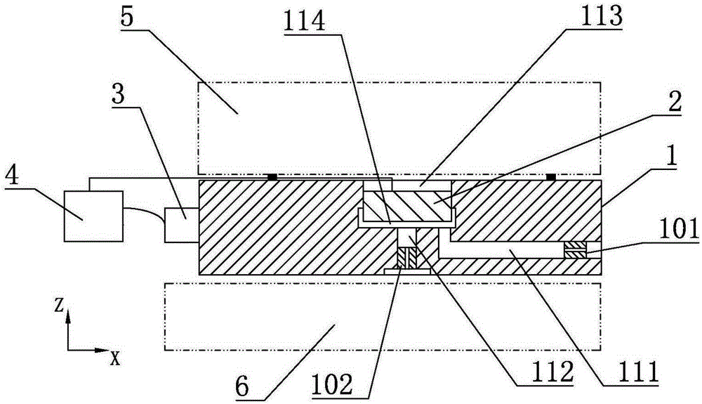
[0022] refer to figure 1 , an air bearing device that actively regulates the air pressure at the inlet of an orifice, including an air bearing body 1, an air pressure active adjustment unit 2, a support body detection unit 3 and a drive control unit 4, through the deformation of the air pressure active adjustment unit 2 Directly change the air pressure at the orifice inlet of the air bearing, t...


PUM


Abstract

The invention discloses an air-floatation supporting device for actively regulating and controlling the air pressure of a throttling hole inlet. The air-floatation supporting device comprises an air-floatation supporting body, an active air-pressure regulating unit, a supporting body detecting unit and a driving control unit, wherein an air inlet hole, a throttling hole and a regulating unit mounting hole are formed in the air-floatation supporting body; an air inlet valve and an air outlet valve are arranged at the air inlet of the air inlet hole and the air outlet of the throttling hole respectively; a regulating cavity is formed between the active air-pressure regulating unit and the air-floatation supporting body; the supporting body detecting unit is used for real-time detection of the speed and acceleration of up-and-down motion of the air-floatation supporting body and / or the distance of the air-floatation supporting body relative to an air-floatation guide rail below the air-floatation supporting body; and the driving control unit is used for performing filtering, amplification and data processing of signals detected by a detecting device to generate driving signals to drive the active air-pressure regulating unit to deform to change the volume of the regulating cavity. The air-floatation supporting device can effectively inhibit micro-vibration of air-floatation supporting and meanwhile has the characteristics of compact structure, convenience in control and high precision.

Description

technical field [0001] The invention belongs to the field of air-floating support devices, and more specifically relates to an air-floating support device that actively regulates the air pressure at the inlet of an orifice. Background technique [0002] The air bearing device is mainly used in ultra-precision processing equipment to support precision moving parts. Compared with the traditional mechanical contact guide rail support, there is no direct contact between the moving parts of the air bearing and the support, which avoids contact friction during the movement, and the movement accuracy can be greatly improved. Therefore, in ultra-precision machining and electronic manufacturing , precision measurement, zero-gravity simulation and other fields, the air flotation support device has been widely used. [0003] The basic form of the air bearing device is that compressed air flows into the gap between the moving part and the supporting part after passing through a small h...

Claims


Application Information

Patent Timeline
Patent Type & Authority Applications(China)
IPC IPC(8): F16C32/06
Inventor 姜伟陈学东朱定玉
Owner HUAZHONG UNIV OF SCI & TECH
Learn More