Magnetorheological Transmission Device

A kind of transmission device and magneto-rheological technology, applied in the direction of brake type, fluid clutch, fluid resistance brake, etc., can solve the problem of poor torque/weight ratio and achieve the effect of improving the effect

Active Publication Date: 2015-12-23
INVENTUS ENG
View PDF5 Cites 9 Cited by
  • Summary
  • Abstract
  • Description
  • Claims
  • Application Information

AI Technical Summary

Problems solved by technology

[0016] Disadvantages of the known magneto-rheological clutches are the requirement of high magnetic field strengths and certain structural dimensions resulting from parameters such as effective diamet

Method used


Image

  • Magnetorheological Transmission Device
  • Magnetorheological Transmission Device
  • Magnetorheological Transmission Device

Examples


Embodiment Construction

[0184] Embodiments of the magneto-rheological transmission device 1 of the present invention will be described below with reference to the accompanying drawings, where identical or similar components bear the same reference numerals.

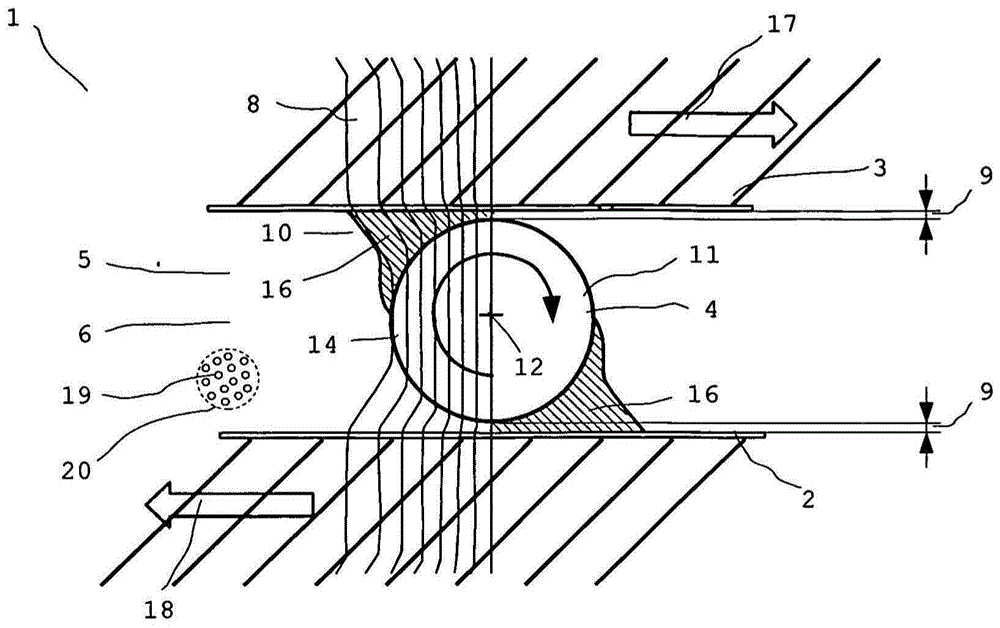
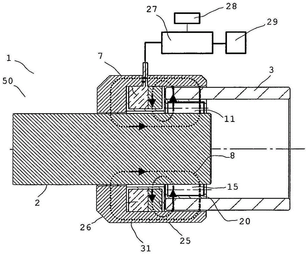
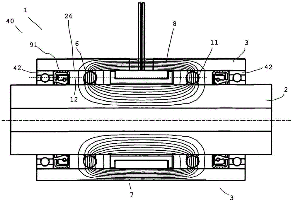
[0185] figure 1 A very schematic cross-sectional view of a magneto-rheological transmission device 1 according to the invention for influencing the force transmission between two components 2 and 3 is shown. At this time, at figure 1 Between the two parts 2 and 3 there is a rotating body 11 as a separate component 4 . The rotating body 11 is here in the shape of a ball 14 . However, it is possible for the rotating body 11 to be in the form of a cylinder or ellipsoid, a roller or another rotatable rotating body. Rotating bodies that are not rotationally symmetrical in the original sense, such as the gear wheel 34 or the rotating body 11 with a certain surface structure, can also be used as the rotating body. The rotors 11 are not used for mut...


PUM


Abstract

Magnetorheological transmission device and method for influencing the coupling intensity of two components, which can be coupled and whose coupling intensity can be influenced. A channel is provided, which contains a magnetorheological medium with magnetically polarizable particles, which can be influenced by a magnetic field. A magnetic field generating unit generates a magnetic field in the channel in order to influence the magnetorheological medium in the channel. A body is disposed in the channel. A free distance between the body and the component is at least ten times greater than a typical mean diameter of the magnetically polarizable particles in the magnetorheological medium. A space with magnetorheological medium is disposed between the body and a component.; The magnetic field is applied to the region in order to optionally chain together the particles and/or wedge or release them with the body.

Description

[0001] This application is a divisional application of an invention patent application with an international filing date of September 15, 2011, an application number of 201180044538.7 (PCT / EP2011 / 004623), and an invention title of "magneto-rheological transmission device". technical field [0002] The invention relates to a magneto-rheological transmission device, in particular a magneto-rheological force or torque transmission device, wherein the transmission between a first component and at least one second component that is movable or stationary relative to the first component can be achieved by The magnetorheological properties of the liquid between these two components are changed. For example, the present invention may selectively reduce drive shaft torque toward the driven shaft. [0003] The magneto-rheological transmission device of the present invention can be applied in many technical fields, for example in vehicles or industrial equipment as clutches or brakes, or ...

Claims


Application Information

Patent Timeline
IPC IPC(8): F16D37/02F16D57/00
CPCA61F2/70A61F2002/5004F16C33/6688F16C2210/06F16D37/02F16D57/002F16D2037/002F16D2037/005F16F9/535
Inventor 斯特凡·巴特洛格
Owner INVENTUS ENG
Why Eureka
Try Eureka