
Switch cabinet temperature measurement control and adjustment device

A control and regulation, switchgear technology, applied in the direction of panel/switch station circuit device, measurement device, substation/switchgear cooling/ventilation, etc. Contact temperature rise and other problems, to achieve the effect of eliminating social adverse effects, reducing contact burnout, and reasonable temperature

Inactive Publication Date: 2015-12-23
ZAOZHUANG POWER SUPPLY COMPANY OF STATE GRID SHANDONG ELECTRIC POWER +1
View PDF0 Cites 5 Cited by
  • Summary
  • Abstract
  • Description
  • Claims
  • Application Information

AI Technical Summary

Problems solved by technology

[0002] With the upgrading of power equipment, most of the power plants and substations currently adopt the power transmission method of fully enclosed switch cabinets. The closed switch cabinets cannot be opened during operation, so it is impossible to measure the actual conditions of the joints and contacts in the cabinet during operation. temperature
Contact heating accidents in sealed switchgear have an increasing trend in recent years, and have become a problem that seriously affects safety production
Important equipment such as high-voltage switchgear operates in a complex environment for a long time, and the live contacts inside the equipment are easy to loosen and oxidize. In the case of overload operation or poor installation, the surface contact resistance will gradually increase. When the load current flows, The temperature of the contacts will rise, or even burn out, causing large-scale power outages, which poses a great safety hazard

Method used


Image

  • Switch cabinet temperature measurement control and adjustment device

Examples


Embodiment Construction

[0011] The following will clearly and completely describe the technical solutions in the embodiments of the present invention with reference to the accompanying drawings in the embodiments of the present invention. Obviously, the described embodiments are only some, not all, embodiments of the present invention. Based on the embodiments of the present invention, all other embodiments obtained by persons of ordinary skill in the art without making creative efforts belong to the protection scope of the present invention.

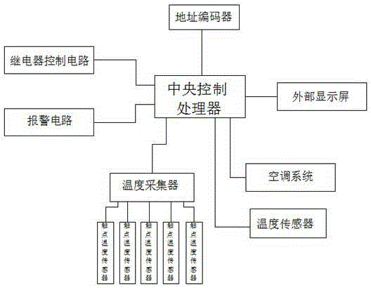
[0012] see figure 1 , in an embodiment of the present invention, a switchgear temperature measurement control adjustment device, including a central control processor, the central control processor is respectively connected with an alarm circuit, a relay control circuit, an address encoder, an external display screen, an air conditioning system, a temperature The sensor is connected to the temperature collector, the temperature collector is connected to the co...


PUM


Abstract

The invention discloses a switch cabinet temperature measurement control and adjustment device, which comprises a central control processor. The central control processor is respectively connected with an alarming circuit, a relay control circuit, an address encoder, an outer display screen, an air conditioning system, a temperature sensor and a temperature collector, and the temperature collector is connected with the contact temperature sensor. According to the switch cabinet temperature measurement control and adjustment device, the structure is simple; temperature of each joint and each contact can be monitored in real time; real-time temperature exceeding alarming is carried out; temperature of joints and contacts inside the switch cabinet or a ring main unit and the like can be monitored in real time; temperature rise conditions of the joints and the contacts are known; temperature inside the cabinet can be adjusted reasonably; the temperature condition of each contact can be known clearly; and in the case of over high temperature, circuit conditions can be quickly controlled, and accidents such as the damaged switch cabinet contact and large-area power failure caused as the joints or the contacts are over heated can be prevented from happening.

Description

technical field [0001] The invention relates to a temperature measuring and regulating device, in particular to a temperature measuring and controlling regulating device for a switch cabinet. Background technique [0002] With the upgrading of power equipment, most of the power plants and substations currently adopt the power transmission method of fully enclosed switch cabinets. The closed switch cabinets cannot be opened during operation, so it is impossible to measure the actual conditions of the joints and contacts in the cabinet during operation. temperature. Contact heating accidents in sealed switchgear have an increasing trend in recent years, and have become a problem that seriously affects safety production. Important equipment such as high-voltage switchgear operates in a complex environment for a long time, and the live contacts inside the equipment are easy to loosen and oxidize. In the case of overload operation and poor installation, the surface contact resis...

Claims


Application Information

Patent Timeline
IPC IPC(8): G01K13/00H02B1/24H02B1/56
Inventor 曹正伦朱福才李思徳尹旭文李槟王伟
Owner ZAOZHUANG POWER SUPPLY COMPANY OF STATE GRID SHANDONG ELECTRIC POWER
Learn More