High-speed rail vertical damper and vehicle body end part longitudinal damper damping coefficient collaborative optimization method

A vertical shock absorber and end longitudinal technology, applied in the direction of instruments, electrical digital data processing, special data processing applications, etc., can solve the problems of dynamic analysis and calculation difficulties and unsatisfactory

Inactive Publication Date: 2015-12-23
SHANDONG UNIV OF TECH
View PDF2 Cites 2 Cited by
  • Summary
  • Abstract
  • Description
  • Claims
  • Application Information

AI Technical Summary

Problems solved by technology

However, according to the available information, since the high-speed rail is a multi-degree-of-freedom vibration system, it is very difficult to perform dynamic analysis and calculation on it. The design of the damping coefficient has not given a systematic theoretical design method. Most of them are the primary vertical shock absorber, the secondary vertical shock absorber and the longitudinal shock absorber at the end of the car body. Technology, using the multi-body dynamics simulation software SIMPACK or ADAMS/Rail, respectively through solid modeling to optimize and determine its size, although this method can get more reliable simulation values, so that the vehicle has better dynamic performance, however, due to The first-series vertical shock absorber, the second-series vertical shock absorber, and the longitudinal shock absorber at the end of the car body ...

Method used


Image

  • High-speed rail vertical damper and vehicle body end part longitudinal damper damping coefficient collaborative optimization method
  • High-speed rail vertical damper and vehicle body end part longitudinal damper damping coefficient collaborative optimization method
  • High-speed rail vertical damper and vehicle body end part longitudinal damper damping coefficient collaborative optimization method

Examples


Embodiment Construction

[0032] specific implementation plan

[0033] The present invention will be further described in detail through an embodiment below.

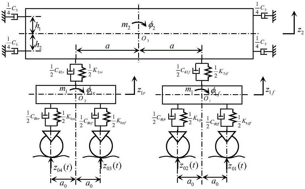
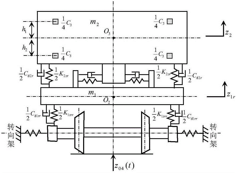
[0034] Each bogie of a high-speed railway is equipped with two first-series front vertical shock absorbers, two first-series rear vertical shock absorbers, two second-series vertical shock absorbers, and two adjacent car bodies are installed with Four longitudinal shock absorbers at the end of the car body, namely n 1 = 2, n 2 = 2, n 3 = 2, n 4 =4; the mass m of its single car body 2 =63966kg, nodding moment of inertia J 2φ =2887500kg.m 2 ; Mass of each bogie frame m 1 =2758kg, nodding moment of inertia J 1φ =2222kg.m 2 ;The vertical equivalent stiffness K of the front suspension of the front bogie 1zff =2.74×10 6 N / m, the vertical equivalent stiffness K of the primary rear suspension 1zfr =2.74×10 6 N / m; vertical equivalent stiffness K of the rear bogie primary front suspension 1zrf =2.74×10 6 N / m, the vertical equivalent stiffne...


PUM


Abstract

The present invention relates to a high-speed rail vertical damper and vehicle body end part longitudinal damper damping coefficient collaborative optimization method, and belongs to the technical field of high-speed railway vehicle suspension technology. A high-speed rail complete vehicle six degree-of-freedom vertical vibration collaborative optimization simulation model is established, track longitudinal irregularity is used as an input stimulus, minimization of a root mean square value of weighed vibration acceleration is the design object, and optimal damping coefficients of primary vertical, secondary vertical and vehicle body end part longitudinal dampers of a high-speed rail are obtained through design optimization. Through design examples and SIMPACK simulation verification, damping coefficients of the primary vertical, secondary vertical and vehicle body end part longitudinal dampers can be accurately and reliably obtained through the method, and a reliable design method is provided for the design of the damping coefficients of the primary vertical, secondary vertical and vehicle body end part longitudinal dampers. By using the method, the design level of a high-speed railway suspension system is raised, vehicle travelling safety and stability are raised, and design and testing expenses are also reduced.

Description

technical field [0001] The invention relates to a high-speed rail vehicle suspension, in particular to a collaborative optimization method for the damping coefficient of the high-speed rail vertical and the longitudinal shock absorber at the end of the car body. Background technique [0002] The first series of vertical shock absorbers, the second series of vertical shock absorbers and the longitudinal shock absorbers at the end of the car body have an important impact on the ride comfort and safety of high-speed rail. However, according to the available information, since the high-speed rail is a multi-degree-of-freedom vibration system, it is very difficult to perform dynamic analysis and calculation on it. The design of the damping coefficient has not given a systematic theoretical design method. Most of them are the primary vertical shock absorber, the secondary vertical shock absorber and the longitudinal shock absorber at the end of the car body. Technology, using the...

Claims


Application Information

Patent Timeline
IPC IPC(8): G06F17/50
Inventor 周长城于曰伟
Owner SHANDONG UNIV OF TECH
Why Eureka
Try Eureka