Efficient electric power cabinet dehumidification device

A power cabinet, high-efficiency technology, applied in the cooling/ventilation of substation/switchgear, etc., can solve the problems of great influence on the safe operation of electrical equipment, poor dehumidification effect, power company losses, etc.

Active Publication Date: 2015-12-23
宝之川电气设备有限公司
View PDF4 Cites 19 Cited by
  • Summary
  • Abstract
  • Description
  • Claims
  • Application Information

AI Technical Summary

Problems solved by technology

[0002] The power cabinet is generally made of cold-rolled steel plate or alloy to store computers and related control equipment. It can provide protection for storage equipment, shield electromagnetic interference, and arrange equipment in an orderly and orderly manner to facilitate future maintenance of equipment. In the power system Among them, the air humidity has a great influence on the safe operation of electrical equipment, and the switch cabinet door can only be used for ventilation, heat dissipation and dehumidification according to the situation, ...

Method used


Image

  • Efficient electric power cabinet dehumidification device
  • Efficient electric power cabinet dehumidification device
  • Efficient electric power cabinet dehumidification device

Examples


Embodiment 1

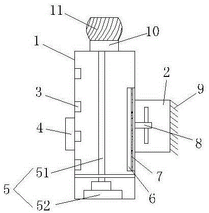
[0020] see figure 1 , the present invention provides a technical solution: a high-efficiency power cabinet dehumidification device, including a cabinet body 1, the back of the cabinet body 1 is provided with a heat dissipation chamber 2, and the air outlet of the heat dissipation chamber 2 is provided with heat dissipation scales 9, And the cooling fan 8 is installed in the inner cavity of the heat dissipation warehouse 2, the inner wall of the cabinet body 1 is provided with a drying layer 6 corresponding to the position of the heat dissipation warehouse 2, and the middle part of the drying layer 6 is equipped with a heating net 7, by setting Some drying layers 6 and cooling fans 8 cooperate with each other to dry the humid air in the cabinet 1 first and then discharge it to avoid backflow of the humid air. The desiccant filled in the inner cavity of the drying layer 6 is activated mineral drying Desiccant or silica gel desiccant, through the middle of the drying layer 6 is p...

Embodiment 2

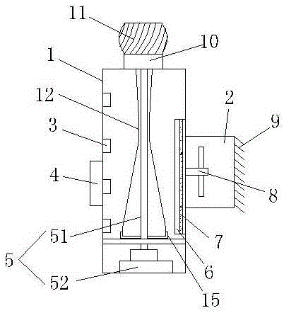
[0023] In the dehumidification device provided in Example 1, when the external wind force is strong, the external wind will be sucked into the ventilation duct 10 at a high speed while the non-powered fan 11 is rotating at a high speed, and some sand and dust will be sucked in when a large amount of wind enters. Inward, resulting in internal pollution of the power cabinet, causing damage to the power facilities inside the power cabinet. Based on the above technical problems, this embodiment makes further improvements on the basis of the dehumidification device provided in embodiment 1.

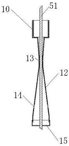
[0024] as attached figure 2 and attached image 3 As shown, in this embodiment, a Venturi tube 12 is installed at the bottom of the ventilation duct 10, the bottom opening of the ventilation duct 10 is connected with the air inlet of the Venturi tube 12, and a suction port is provided at the throat of the Venturi tube 10. The air hole 13, the skirt of the Venturi tube 12 diffusion cavity is...


PUM


Abstract

The invention discloses an efficient electric power cabinet dehumidification device. The efficient electric power cabinet dehumidification device comprises a cabinet body, wherein a heat radiation cabin is arranged at the back part of the cabinet body; a heat radiation fan is mounted in the inner cavity of the heat radiation cabin; a drying layer is arranged on the inner wall of the cabinet body and at a part corresponding to the position of the heat radiation cabin; a heating net is mounted in the middle of the drying layer; a plurality of temperature sensors are arranged on the inner wall of the cabinet body; and the temperature sensors are electrically connected with a control panel. Through the mutual matching of the drying layer and the heat radiation fan, humid air in the cabinet can be dried so that the humid air is prevented from reflowing; the heating net is arranged in the middle of the drying layer so that a drying agent in the drying layer can be used for a plurality of times and does not lose effect; a powerless draught fan at the top of the cabinet body and a wind motor arranged at the bottom are mutually matched, so that power can be supplied to electric appliances in a whole process and a reserve power supply also can be provided; and meanwhile, the powerless draught fan also can be used for exchanging air in the cabinet body.

Description

technical field [0001] The invention relates to the technical field of dehumidification devices, in particular to a high-efficiency power cabinet dehumidification device. Background technique [0002] The power cabinet is generally made of cold-rolled steel plate or alloy to store computers and related control equipment. It can provide protection for storage equipment, shield electromagnetic interference, and arrange equipment in an orderly and orderly manner to facilitate future maintenance of equipment. In the power system Among them, the air humidity has a great influence on the safe operation of electrical equipment, and the switch cabinet door can only be used for ventilation, heat dissipation and dehumidification according to the situation, the dehumidification effect is poor, and it is greatly affected by the external environment. The company caused immeasurable losses. [0003] Compared with high-efficiency power cabinets, high-temperature evaporation cannot be us...

Claims


Application Information

Patent Timeline
IPC IPC(8): H02B1/56
Inventor 唐宁许宏力鞠章建张淼张杰李冉
Owner 宝之川电气设备有限公司
Why Eureka
Try Eureka