
Medical centrifugal pump head

A pump head and pump casing technology, which is applied in the field of medical auxiliary equipment production, can solve the problems of blood stagnation, thrombus, blood cell destruction, etc., and achieve the effect of improving effect, reducing heat production, and reducing heat

Pending Publication Date: 2021-12-10
卡迪美科北京生物科技有限公司
View PDF0 Cites 2 Cited by
  • Summary
  • Abstract
  • Description
  • Claims
  • Application Information

AI Technical Summary

Problems solved by technology

In the traditional centrifugal pump head, due to the friction at the seal of the induction wheel shaft, when the centrifugal pump runs at high speed, it will generate a lot of heat, which will easily lead to the destruction of blood cells, and the stagnation of blood at the seal of the induction wheel shaft will also easily lead to thrombus.

Method used


Image

  • Medical centrifugal pump head
  • Medical centrifugal pump head
  • Medical centrifugal pump head

Examples


Embodiment Construction

[0028] The medical centrifugal pump of the present invention can be made of the following materials, but not limited to the following materials, for example: plastics, magnets, ceramics, silica gel, polycarbonate and the like.

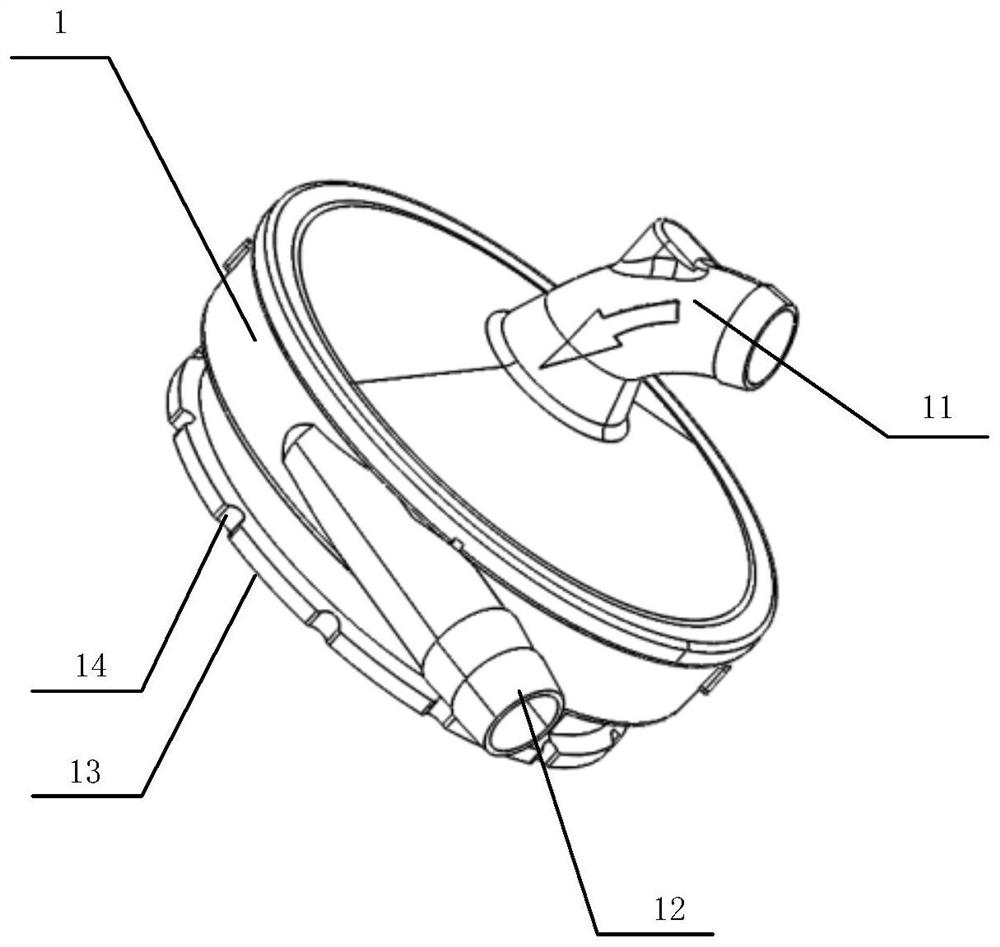
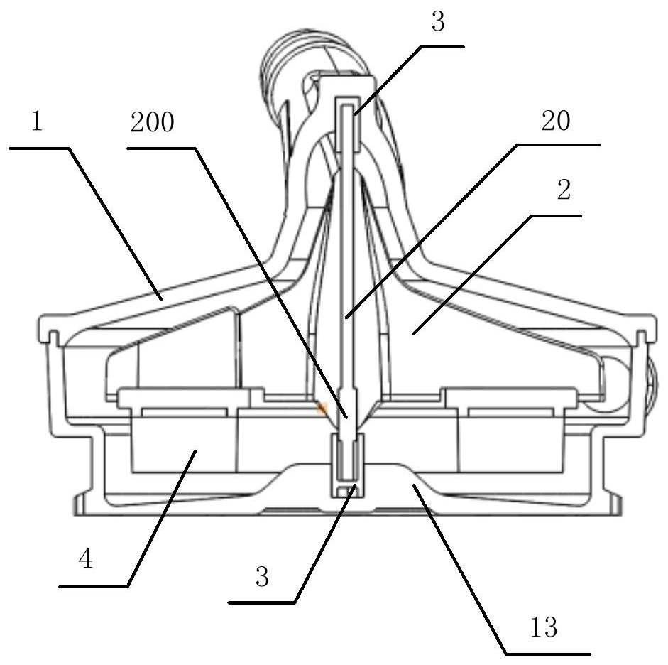
[0029] figure 1 It is the overall schematic diagram of the medical centrifugal pump head of the embodiment of the present invention, combined with Figure 2 to Figure 6 , the medical centrifugal pump head of the present embodiment, comprising: comprising: a pump casing 1, and an inducer 2 rotatably installed in the pump casing 1; a magnet 4 is provided at the bottom of the inducer 2; when an external magnetic force is established When driving, the inner induction wheel 2 starts to rotate under the drive of the magnet 4, thereby realizing the function of the centrifugal pump head.

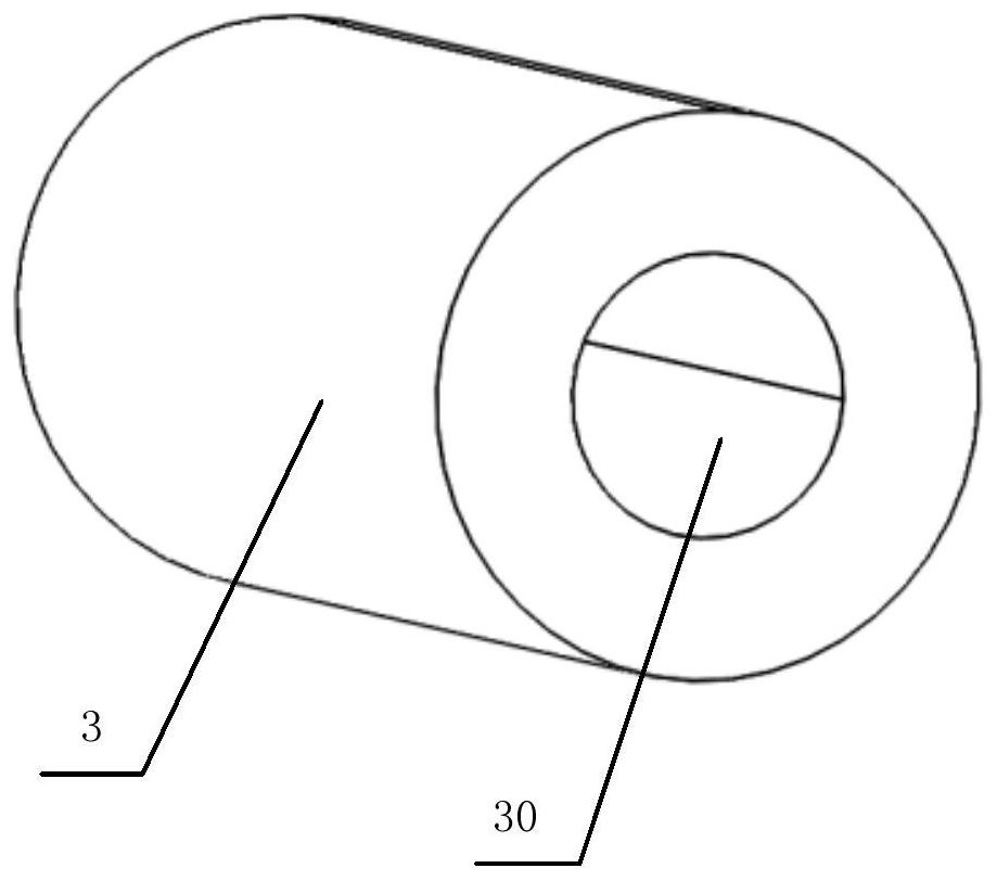
[0030] The pump housing 1 is provided with a liquid inlet 11 and a liquid outlet 12; the pump housing 1 is provided with a top positioning sleeve and a bottom positioning s...


PUM


Abstract

The invention relates to the technical field of medical treatment, and particularly relates to a medical centrifugal pump head. The medical centrifugal pump head comprises a pump shell and an inducer rotationally installed in the pump shell; a magnet is arranged at the bottom of the inducer; the pump shell is provided with a liquid inlet and a liquid push-out opening; a top positioning sleeve and a bottom positioning sleeve are arranged in the pump shell; a positioning rod capable of rotating around the inducer is arranged at the axis of the inducer, and the two ends of the positioning rod are respectively connected with the top positioning sleeve and the bottom positioning sleeve; the section of the liquid inlet is gradually increased in the liquid inflow direction, and the liquid inlet is located in the center of the top of the pump shell; a plurality of blades with inclined side surfaces are arranged on the inducer, and an angle between the liquid push-out opening and the blades is 45 degrees; and a plurality of positioning notches capable of being connected with external equipment are formed in the bottom of the pump shell. The medical centrifugal pump head adopts the bearing-free design, is less in friction and lower in heat production, ensures that no vortex exists in a liquid inlet and the liquid push-out opening of the centrifugal pump head, is uniform in acceleration, and keeps the optimal blood flow.

Description

technical field [0001] The invention relates to the manufacturing technology of medical supplies, and more specifically relates to a medical centrifugal pump head, which belongs to the technical field of medical auxiliary equipment production. Background technique [0002] The application fields of medical centrifugal pump head mainly include extracorporeal circulation in cardiac surgery, ventricular assisted circulation, heart transplantation, extracorporeal membrane lung support, aortic surgery, liver and kidney transplantation, and extracorporeal circulation. In the traditional centrifugal pump head, due to the friction at the seal of the induction wheel shaft, when the centrifugal pump runs at high speed, it will generate a lot of heat, which will easily lead to the destruction of blood cells, and the stagnation of blood at the seal of the induction wheel shaft will also easily lead to thrombus. . [0003] Therefore, there is a need in the prior art for a medical centri...

Claims


Application Information

Patent Timeline
Patent Type & Authority Applications(China)
IPC IPC(8): A61M60/104A61M60/232A61M60/806A61M60/81A61M60/812
CPCA61M60/104A61M60/232A61M60/806A61M60/81A61M60/812
Inventor 黄周平
Owner 卡迪美科北京生物科技有限公司
Learn More