Infrared charging system and infrared charging method

A charging system and charging method technology, which are applied in the direction of secondary battery charging/discharging, battery circuit devices, current collectors, etc., can solve the problems of discount on wireless charging, unsatisfactory effective charging distance, low charging efficiency, etc. The effect of improving power supply stability, improving stability and improving utilization rate

Pending Publication Date: 2015-12-23
JIANGSU TENWEI ELECTRONICS
View PDF0 Cites 14 Cited by
  • Summary
  • Abstract
  • Description
  • Claims
  • Application Information

AI Technical Summary

Problems solved by technology

However, the effective charging distance of existing wireless chargers is not ideal, ranging from a few millimeters to tens of centimeters, which greatly reduces the experience of using wireless charging. In addition, the charging efficiency of existing wireless chargers is low, and Only provide power

Method used


Image

  • Infrared charging system and infrared charging method
  • Infrared charging system and infrared charging method
  • Infrared charging system and infrared charging method

Examples


Embodiment 1

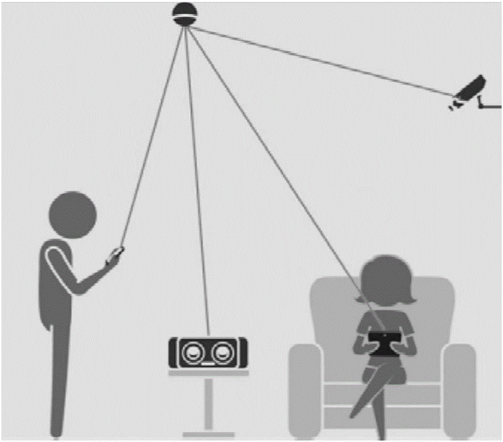
[0025] figure 1 The infrared charging system includes: several infrared charging devices and devices to be charged. The infrared charging devices are at a certain height from the ground. The devices to be charged can be mobile terminals such as mobile phones, tablets, computers, or wearable devices, wireless speakers, keyboards, etc. Auxiliary equipment.

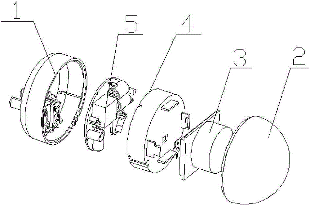
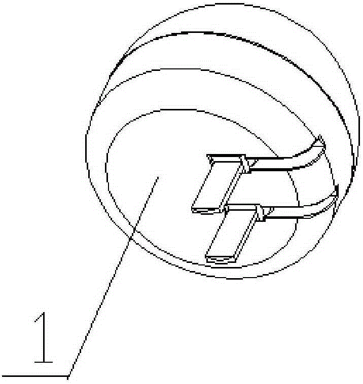
[0026] Above-mentioned infrared charging device can adopt as Figures 2 to 4 As shown in the structure, the infrared charging device includes: a bottom box 1 and an infrared-transmitting surface shell 2, the bottom box 1 adopts a hollow cylindrical structure, and the infrared-transmitting surface shell 2 is a convex hemispherical structure, and the infrared-transmitting surface shell 2 passes through The buckle is fixedly connected with the bottom box 1 to form the inner cavity of the charger; the outer side of the bottom box 1 is provided with a foldable plug, and an isolation bracket 4 is provided between the bottom box 1...

Embodiment 2

[0030] In this embodiment, an example is given to illustrate whether the above-mentioned infrared sending control module decides whether to pair according to the current charging situation in the system. Since the infrared signal transmission power is very small, generally speaking, the power of each laser diode is only nearly 10mA. Take the infrared charging system with 100 laser diodes as an example, as Figure 5 As shown, when only one device to be charged enters the pairable area and the pairing request is successful, 100 transmitting units charge it. At this time, the effective working current of the device to be charged is 1A (5V), and the power is 5W; Image 6 As shown, when 2 devices to be charged enter the pairable area and the pairing request is successful, 100 transmitting units charge the 2 devices to be charged, roughly 50 transmitting units to one. At this time, each device to be charged is effectively The working current is 500MA (5V), and the power is 2.5W; and...

Embodiment 3

[0033] When using the infrared charging system for charging, the infrared charging device can first be laid out according to a pre-designed distribution map, and the distribution map of the infrared charging device can adopt a common cellular structure in mobile communications, that is, the infrared charging system includes multiple hexagonal In the radiation area of ​​the hexagon, infrared charging devices are arranged at each vertex of the hexagon. Adopting such a layout diagram of the charging device can make the power supply capacity of any position in the radiation area of ​​the system the same, provide stable power for the mobile device to be charged, and improve the charging quality.


PUM


Abstract

An infrared charging system disclosed by the present invention comprises a plurality of infrared charging devices and a plurality of to-be-charged devices. The infrared charging devices and the to-be-charged devices establish connection via the infrared ray pairing, so that the to-be-charged devices are charged. The present invention also discloses an infrared charging method. The method comprises the steps that: firstly, the infrared charging devices transform the electric energy into the infrared signals to emit; the to-be-charged devices and the infrared charging devices establish the pairing connection; and the to-be-charged devices receive the infrared signals and transform the infrared signals into the electric energy to store. The infrared charging system and the infrared charging method of the present invention solve the problem that the charging distance of a conventional wireless charger is not ideal, and realize the effects of improving the effective charging distance and the power supply stability of the wireless charger.

Description

technical field [0001] The invention relates to the field of wireless charging, in particular to an infrared charging system and an infrared charging method. Background technique [0002] A wireless charger refers to a charger that is connected to a terminal device that needs to be charged without a traditional charging power cord. The existing wireless charger uses magnetic induction or magnetic resonance technology to transmit electric energy by using the magnetic field generated between coils. , The advantage of wireless charging technology lies in its convenience and versatility. However, the effective charging distance of existing wireless chargers is not ideal, ranging from a few millimeters to tens of centimeters, which greatly reduces the experience of using wireless charging. In addition, the charging efficiency of existing wireless chargers is low, and Provides electrical energy only. Contents of the invention [0003] In order to overcome the deficiencies in t...

Claims


Application Information

Patent Timeline
Patent Type & Authority Applications(China)
IPC IPC(8): H02J7/00H02S10/20H01M10/44
CPCY02E10/50Y02E60/10Y02E70/30
Inventor 张宗升刘翠勤陈彦方小卫李明杰刘俊艳高照斌
Owner JIANGSU TENWEI ELECTRONICS
Why Eureka
Try Eureka