Intelligent monitoring system for visual indoor illumination subareas and control method of intelligent partition monitoring system

An intelligent monitoring system and indoor lighting technology, applied in energy-saving control technology, lighting devices, light sources, etc., can solve problems such as waste of electric energy, limited number of uses, and all lights are turned on, so as to solve adaptability, save electric energy, and solve errors. Effects of Operational or Failure Issues

Inactive Publication Date: 2015-12-23
MIANYANG TEACHERS COLLEGE +1
View PDF6 Cites 4 Cited by
  • Summary
  • Abstract
  • Description
  • Claims
  • Application Information

AI Technical Summary

Problems solved by technology

The main problem of this control method is: when there are few people in the room, the lighting lamps may still be fully turned on, resulting in a waste of electric energy; There are problems such as poor contact after a period of time; if the indoor personnel forget to turn off the light when they leave, there will be a phenomenon of constant light; the manual control method cannot realize the turning on or off of the lighting fixture according to the change of the indoor light
There are two main problems in using ultrasonic ranging method for lighting control: one is that there is a large error in the existing civil ultrasonic ranging, and it is easy to misjudgment when judging whether there is someone; the other problem is when the object (such as When placing items on the desk), especially when the items have a certain height (such as computer monitors, etc.), the applicability of the ultrasonic distance measurement method for lighting control is limited
[0008] In order to realize the intelligent control of indoor lighting, researchers have conducted a lot of research, and some have combined several control methods, but none of them have achieved the desired results so far.

Method used


Image

  • Intelligent monitoring system for visual indoor illumination subareas and control method of intelligent partition monitoring system
  • Intelligent monitoring system for visual indoor illumination subareas and control method of intelligent partition monitoring system
  • Intelligent monitoring system for visual indoor illumination subareas and control method of intelligent partition monitoring system

Examples


Embodiment Construction

[0032] All features disclosed in this specification, or steps in all methods or processes disclosed, may be combined in any manner, except for mutually exclusive features and / or steps.

[0033] Any feature disclosed in this specification (including any appended claims, abstract and drawings), unless expressly stated otherwise, may be replaced by alternative features which are equivalent or serve a similar purpose. That is, unless expressly stated otherwise, each feature is one example only of a series of equivalent or similar features.

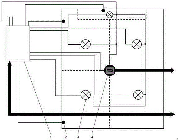
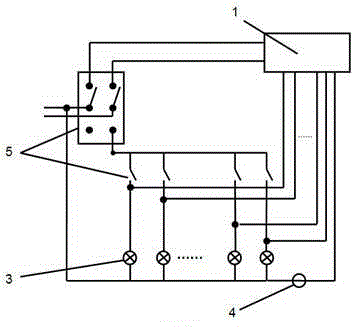
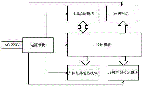
[0034] by attaching Figure 1-4 It can be seen that the present invention includes a lamp group, a control box, a camera and a server; the control box is connected to the infrared sensor, the ambient light intensity detector and the server respectively; the camera is connected to the server through the network; the lamp group is connected to the switch assembly; the server It can receive the signals transmitted by the control box and th...


PUM


Abstract

The invention provides a technical scheme including an intelligent monitoring system for visual indoor illumination subareas and a control method of the intelligent monitoring system. The intelligent monitoring system comprises a lamp bank, a control box, a camera and a server, wherein the control box is connected with an infrared sensor, an ambient light intensity detector and the server respectively; the camera is connected with the server through a network; the lamp bank is connected with a switch assembly; the server can receive signals transmitted by the control box and the camera; and the server can control opening and closing of the switch assembly and the camera through the control box. According to the intelligent monitoring system and the control method, with an indoor video image as a control signal source, by combination of infrared induction and light intensity detection, automatic and intelligent control on the indoor subarea illumination is achieved; and the problems in a plurality of control modes at present are effectively solved.

Description

technical field [0001] The invention relates to a lighting control system, in particular to a visualized indoor lighting partition intelligent monitoring system and a control method thereof. Background technique [0002] At present, there are mainly the following methods for indoor lighting control: manual control, infrared sensor control, sound control, time-based control, ultrasonic distance measurement control, etc. [0003] In the manual control mode, a mechanical switch is generally installed near the entrance and exit of the room, and the lighting is turned on when a person enters the room. The main problem of this control method is: when there are few people in the room, the lighting lamps may still be fully turned on, resulting in a waste of electric energy; There are problems such as poor contact after a period of time; if the indoor personnel forget to turn off the light when they leave, there will be a phenomenon of constant light; the manual control method canno...

Claims


Application Information

Patent Timeline
Patent Type & Authority Applications(China)
IPC IPC(8): H05B37/02
CPCY02B20/40
Inventor 郭兴吉彭声泽赵秋月李淑珍文永革焦家明
Owner MIANYANG TEACHERS COLLEGE
Why Eureka
Try Eureka