Intravascular ultrasound diagnostic instrument with rotation coupled structure

An ultrasonic diagnostic instrument and a coupling structure technology, which is applied in the field of vascular diagnostic instruments, can solve problems such as cost waste, and achieve the effects of improving conduction performance, reducing use cost and optimizing coupling structure.

Active Publication Date: 2015-12-30
上海爱声生物医疗科技有限公司
View PDF7 Cites 5 Cited by
  • Summary
  • Abstract
  • Description
  • Claims
  • Application Information

AI Technical Summary

Problems solved by technology

[0004] For mechanical rotating ultrasonic catheters, the current products on the market connect the coupling structure with a disposable catheter, which is discarded after one use, causing a lot of waste in terms of cost

Method used


Image

  • Intravascular ultrasound diagnostic instrument with rotation coupled structure
  • Intravascular ultrasound diagnostic instrument with rotation coupled structure
  • Intravascular ultrasound diagnostic instrument with rotation coupled structure

Examples


Embodiment 1

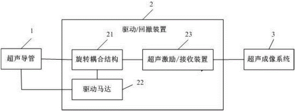
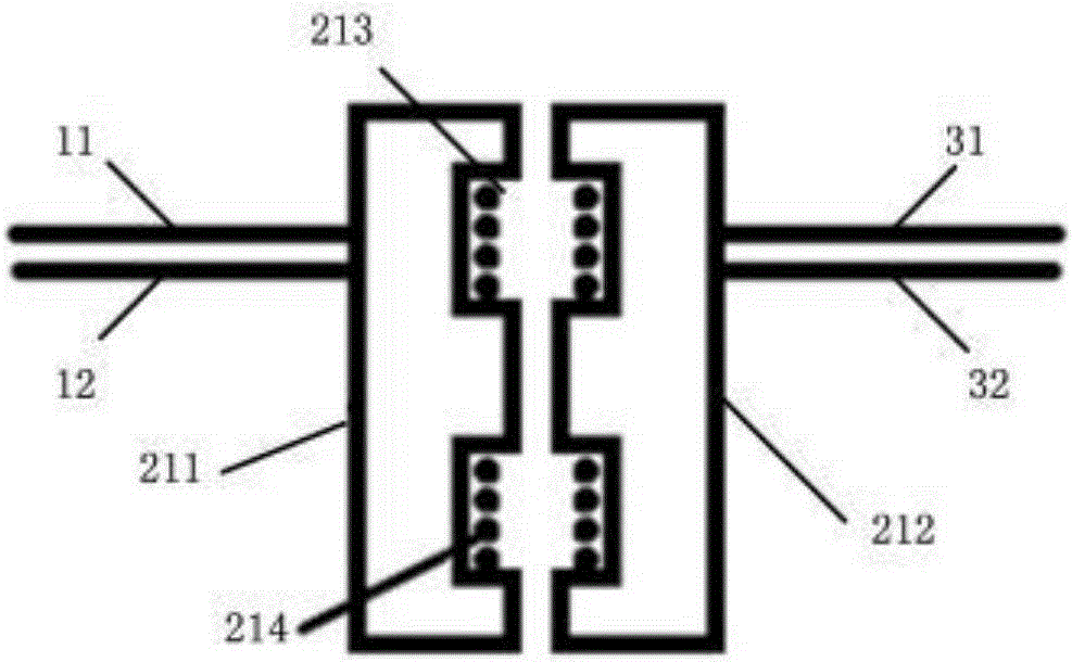
[0037] The rotary coupling structure of this embodiment is a rotary transformer coupling structure, and its structural schematic diagram is as follows figure 2 As shown, it includes: two magnetic cores, one is a fixed magnetic core 211, and the other is a rotating magnetic core 212. The fixed magnetic core 211 is connected to the signal line 31 and the ground wire 32 of the ultrasonic imaging system, and the rotating magnetic core 212 is connected to the transducer The signal line 11 of the device is connected to the ground line 12. The two magnetic cores are arranged face to face, and grooves 213 are arranged on the opposite surfaces. The signal lines 11 and 31 pass through the backs of the magnetic cores 211 and 212 respectively and wind in the grooves 213. The coil 214 has four turns as shown in the figure, and there is no limitation here, and different numbers of turns can be made according to different performance requirements. When working, the driving motor 22 drives t...

Embodiment 2

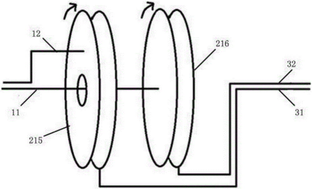
[0040] The rotary coupling structure of this embodiment is a rotary capacitive coupling structure, and its structural schematic diagram is as follows image 3 As shown, it includes: two capacitors, respectively a first capacitor 215 and a second capacitor 216, the left part of the two capacitors is a rotating part, the right part is a fixed part, the left part of the first capacitor 215 is in contact with the switching part. The signal line 11 of the transducer is connected, the left part of the second capacitor 216 is connected with the ground wire 12 of the transducer, the right part of the first capacitor 215 is connected with the signal line of the ultrasonic imaging system, and the right part of the second capacitor 216 Part of it is connected to the ground wire 32 of the ultrasound imaging system, and the two capacitors are arranged coaxially. When working, the driving motor 22 drives the left part of the two capacitors to rotate, and at the same time drives the transduc...


PUM


Abstract

The invention discloses an intravascular ultrasound diagnostic instrument with a rotation coupled structure. The intravascular ultrasound diagnostic instrument comprises an ultrasound catheter, a driving/withdrawing device and an ultrasound imaging system, wherein one end of the driving/withdrawing device is connected with the ultrasound catheter, and the other end is connected with the ultrasound imaging system; the driving/withdrawing device comprises the rotation coupled structure, a driving motor and an ultrasound excitation/reception device; one end of the rotation coupled structure is connected with the ultrasound catheter, and the other end of the rotation coupled structure is connected with the ultrasound excitation/reception device; the ultrasound excitation/reception device is connected with the ultrasound imaging system; the driving motor is connected with the rotation coupled structure, and is also connected with the ultrasound catheter. According to the intravascular ultrasound diagnostic instrument with the rotation coupled structure, the rotation coupled structure is arranged in the driving/withdrawing device, so that the using cost is reduced, and meanwhile, the possibility is provided for improving the performance of the rotation coupled structure.

Description

technical field [0001] The invention relates to a blood vessel diagnostic instrument, in particular to an intravascular ultrasonic diagnostic instrument with a rotating coupling structure. Background technique [0002] Intravascular Ultrasound (IVUS) is a new diagnostic method combining non-invasive ultrasound technology and minimally invasive catheter technology. Intravascular ultrasound is to use catheter technology to introduce a high-frequency micro-ultrasound transducer into the blood vessel cavity for detection, and obtain cross-sectional imaging of each layer of the blood vessel wall to assist clinicians in diagnosing intravascular lesions. [0003] An intravascular ultrasound imaging system consists of three main components, such as figure 1 As shown, an intravascular ultrasound catheter 1 equipped with an ultrasound probe, a retraction / driving device 2 and an ultrasound imaging system 3 are shown. There are two main designs of commercialized IVUS catheters: mechan...

Claims


Application Information

Patent Timeline
Patent Type & Authority Applications(China)
IPC IPC(8): A61B8/12
Inventor 陈友伟李翔赵万金
Owner 上海爱声生物医疗科技有限公司
Why Eureka
Try Eureka