Method for conducting oriented solidification on CET refining metal solidification organization under longitudinal magnetic field

A technology of directional solidification and longitudinal magnetic field, which is applied in the field of metal material remelting and casting processing, can solve the problems of affecting the scope of refinement, melt splashing, splashing, etc., to avoid chilling effect or pollution, prevent liquid splashing, and ensure safety high effect

Active Publication Date: 2015-12-30
SHANGHAI UNIV
View PDF6 Cites 7 Cited by
  • Summary
  • Abstract
  • Description
  • Claims
  • Application Information

AI Technical Summary

Problems solved by technology

In the technology of ultrasonically refining metal solidification structure, it is a key technology to introduce the ultrasonic heat-resistant tool head into the metal melt. At the same time, due to the serious dissipation of ultrasonic waves in the metal melt, its thinning effect is limited, which also limits In the technology of pulse current refining metal solidification structure, the contact between the electrode and the melt may cause chilling effect or pollution, and the current directly passes through the metal melt. If the current is too large, it will easily cause the melt to splash. Small, it will cause the newly formed grains to remelt in the high temperature melt, weakening the refining effect; Large, strong magnetic fields will also cause strong fluctuations and even splashes on the metal surface
In particular, in the technology of refining the metal solidification structure in the electromagnetic field, the skin effect will occur in the melt whether it is an externally applied or induced alternating current, which seriously affects the refining range.

Method used


Image

  • Method for conducting oriented solidification on CET refining metal solidification organization under longitudinal magnetic field
  • Method for conducting oriented solidification on CET refining metal solidification organization under longitudinal magnetic field
  • Method for conducting oriented solidification on CET refining metal solidification organization under longitudinal magnetic field

Examples


Embodiment 1

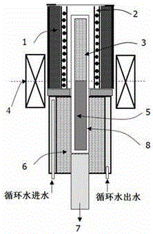
[0026] In this example, see Figure 1 ~ Figure 3 The metal melting and casting device adopted by the directional solidification method of the present invention is composed of a water-cooled jacket 1, a heating furnace 2, a magnet 4, a cooling pool 6, a pull rod 7 and a directional solidification crucible 8, and the directional solidification crucible 8 is heated by the heating furnace 2 to make the metal material melting, the directional solidification crucible 8 is connected to the pull rod 7 of the directional solidification device to form a drawing system, so that it can be pulled in the heating furnace 2 for linear movement, and the pulling of the pull rod 7 and the cooling effect of the cooling pool 6 make the The molten metal material is directional solidified, the upper part in the directional solidification crucible 8 cavity is the alloy rod liquid phase part 3, the lower part in the directional solidification crucible 8 cavity is the alloy rod solid phase part 6, and t...

Embodiment 2

[0033] This embodiment is basically the same as Embodiment 1, especially in that:

[0034] In this example, see Figure 4 , the present embodiment is a method for directional solidification CET to refine metal solidification structure under longitudinal magnetic field, the steps are as follows:

[0035] a. This step is identical with embodiment one;

[0036] b. Metal melting and casting process: corundum tube is used as the directional solidification crucible 8, the inner diameter of the corundum tube is 3mm, the length is 200mm, the magnet 4 is an electromagnet, and the Al-20wt%Cu alloy rod sample is used, the diameter of the alloy rod sample is 2.9mm, and the length is 150mm , and encapsulate it in a corundum tube for later use, put the vertical directional solidification device into a vertical strong magnetic field, which is generated by a magnet 4, connect the corundum tube to the pull rod 7 of the directional solidification device, so that it can Pulling in the heatin...

Embodiment 3

[0039] This embodiment is basically the same as the previous embodiment, and the special features are:

[0040] In this example, see Figure 5 , the present embodiment is a method for directional solidification CET to refine metal solidification structure under longitudinal magnetic field, the steps are as follows:

[0041] a. This step is identical with embodiment one;

[0042] b. Metal melting and casting process: use a corundum tube as the directional solidification crucible 8, the inner diameter of the corundum tube is 3mm, the length is 200mm, the magnet 4 is an electromagnet, and the Al-7wt%Si-1wt%Fe alloy rod sample is used, and the diameter of the alloy rod sample is 2.9 mm, length 150mm, and it is packaged in the corundum tube for standby, the vertical directional solidification device is put into the longitudinal strong magnetic field, and the longitudinal strong magnetic field is produced by the magnet 4, the corundum tube is connected to the pull rod 7 of the di...


PUM

PropertyMeasurementUnit
sizeaaaaaaaaaa
lengthaaaaaaaaaa
diameteraaaaaaaaaa

Abstract

The invention discloses a method for conducting oriented solidification on a CET refining metal solidification organization under a longitudinal magnetic field. The method includes the steps that firstly, an oriented solidification crucible is connected to a pull rod of an oriented solidification device, a drawing and pulling system is formed, and the drawing and pulling system can be drawn and pulled in a heating furnace for conducting linear movement; then, solid metal materials are arranged in the crucible, the furnace temperature of an inner cavity of the heating furnace is heated to a set degree, the metal materials in the crucible are smelted, and heat preservation is conducted on the smelted metal melt according to the set time; then, the drawing and pulling system is started, oriented drawing and pulling is conducted at a set pulling speed, in the drawing and pulling process, the longitudinal magnetic field is applied to the metal melt, and the metal solid liquid interface in the crucible is kept in a steady magnetic field region with set magnetic field intensity all the time; after drawing and pulling is conducted, a solidificated metal stick is obtained. According to the method for conducting oriented solidification on the CET refining metal solidification organization under the longitudinal magnetic field, a Seeback effect is utilized, the longitudinal magnetic field acts on the solid liquid interface generated after oriented solidification is conducted, and columnar crystal is converted into isometric crystal, so that the refining metal solidification organization is obtained.

Description

technical field [0001] The invention relates to a method for preparing a solidified metal structure, in particular to a method for preparing a solidified metal structure with an external magnetic field applied to the technical field of metal material remelting and casting. Background technique [0002] Metal materials have a very important impact on the development and progress of a country. With the rapid development of modern science and technology, people have higher and higher requirements for the performance of metal materials, and the key to obtaining high-quality metal materials is to effectively control the solidification process of metals. Among them, refining the metal solidification structure can not only improve the strength of the material, but also improve the plasticity of the material, and can also significantly improve its mechanical properties. In order to obtain a refined metal solidification structure, researchers have carried out a lot of exploration an...

Claims


Application Information

Patent Timeline
Patent Type & Authority Applications(China)
IPC IPC(8): B22D27/02
Inventor 李喜李寒骁杜大帆关光
Owner SHANGHAI UNIV
Why Eureka
Try Eureka