A low-viscosity high-shear water-in-oil drilling fluid

A drilling fluid and water-in-oil technology, which is applied in the field of drilling fluid, can solve problems affecting gas logging and other problems, and achieve the effect of improving the cuttings-carrying ability

Active Publication Date: 2018-03-23
北京奥凯立科技发展股份有限公司
View PDF8 Cites 0 Cited by
  • Summary
  • Abstract
  • Description
  • Claims
  • Application Information

AI Technical Summary

Problems solved by technology

It is easy to form cuttings bed and affect gas logging

Method used


Image

  • A low-viscosity high-shear water-in-oil drilling fluid
  • A low-viscosity high-shear water-in-oil drilling fluid
  • A low-viscosity high-shear water-in-oil drilling fluid

Examples


Embodiment 2

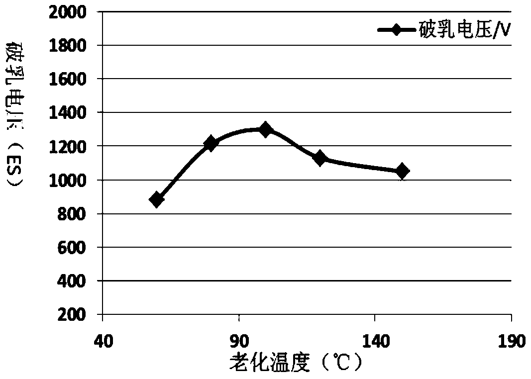
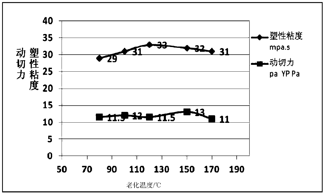
[0064] The formula of the low-viscosity and high-cut water-in-oil drilling fluid used in the following tests is as follows: the water-in-oil base fluid is composed of diesel oil and brine solution in a volume ratio of 85:15; the brine solution is chlorine formed by adding 9 g of calcium chloride to 100 mL of water Calcium hydroxide aqueous solution; based on each 100mL water-in-oil base liquid, the addition amount of the remaining components is: 3 grams of primary emulsifier, 1 grams of auxiliary emulsifier, 4 grams of fluid loss agent [oxidized pitch], 4 grams of calcium oxide, Organic soil 3 grams, plugging agent 3 grams, barite powder 0-150 grams [Barite powder is used to adjust the density of the drilling fluid, which has no effect on the performance of the drilling fluid. Add it according to the density of the drilling fluid used in the test. Known techniques of those skilled in the art].

[0065] Table 8 shows the drilling conditions of the Xushen 8-Gengping 1 well using lo...


PUM

PropertyMeasurementUnit
densityaaaaaaaaaa
densityaaaaaaaaaa
densityaaaaaaaaaa

Abstract

The invention discloses low-viscosity high-cut water-in-oil drilling fluid. The low-viscosity high-cut water-in-oil drilling fluid comprises water-in-oil base fluid, a main emulsifier, an auxiliary emulsifier, a fluid loss additive, calcium oxide, organic soil, a formation sealant and barite powder. The water-in-oil drilling fluid has the characteristics of stable property, facilitation of hole cleaning, increase of the drilling speed, emphasis on formation sealing, guarantee of stable sidewalls and the like.

Description

Technical field [0001] The invention relates to drilling fluid in petroleum drilling engineering. More specifically, it relates to a high-temperature-resistant, low-viscosity, high-cut water-in-oil drilling fluid for special well types such as deep wells, horizontal wells, and branch wells. Background technique [0002] Compared with water-based drilling fluids, oil-based drilling fluids have the advantages of being suitable for water-sensitive formations and large salt formations, protecting oil and gas formations, not corroding drilling tools, and being reusable. They have always been an effective solution to special craft wells. And one of the drilling fluid systems for complex formations. [0003] With the expansion of the field of drilling and development, complex wells and special craft wells have been increasing year by year. In order to improve the drilling success rate, it is necessary to use a water-in-oil drilling fluid with good lubricity and strong well wall stabilit...

Claims


Application Information

Patent Timeline
Patent Type & Authority Patents(China)
IPC IPC(8): C09K8/36
CPCC09K8/36
Inventor 王雷柴奎徐云鹏张金龙张晓坡杨晓岭卢丙朵周文欣王欣李林锋
Owner 北京奥凯立科技发展股份有限公司
Why Eureka
Try Eureka