
Well wall structure and construction method of a water-bearing rock formation

A construction method and shaft wall technology, applied in shaft equipment, earthwork drilling, shaft lining, etc., can solve the problems of unused surrounding rock mass bearing capacity, accumulation, peeling, etc., to improve compactness and bond strength, reduce The effect of thin well wall and lower engineering cost

Active Publication Date: 2017-08-11
CHINA UNIV OF MINING & TECH
View PDF10 Cites 0 Cited by
  • Summary
  • Abstract
  • Description
  • Claims
  • Application Information

AI Technical Summary

Problems solved by technology

In the high water pressure rock formation, the shaft wall structure poured by this process, on the one hand, there is no other bonding and anchoring effect between the shaft wall and the surrounding rock mass except for the natural bonding force between the concrete and the surrounding rock. Give full play to the bearing capacity of the surrounding rock mass itself; on the other hand, once the well wall structure is compressed inward, it is easy to peel off from the surrounding rock mass, resulting in the accumulation of external water pressure and bearing greater water pressure

Method used


Image

  • Well wall structure and construction method of a water-bearing rock formation
  • Well wall structure and construction method of a water-bearing rock formation
  • Well wall structure and construction method of a water-bearing rock formation

Examples


Embodiment 1

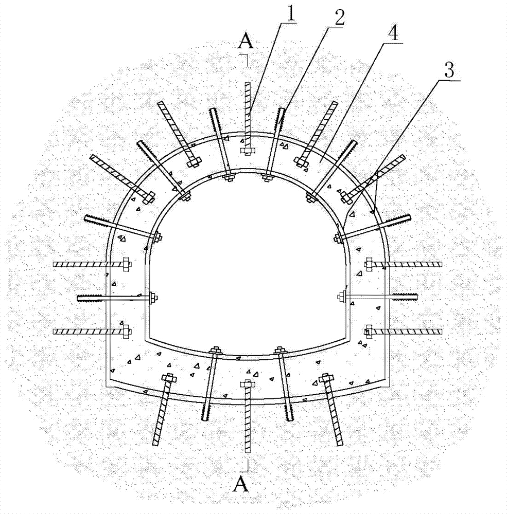
[0046] Example 1: The bottom plate is an inclined shaft wall structure with an inverted arch type

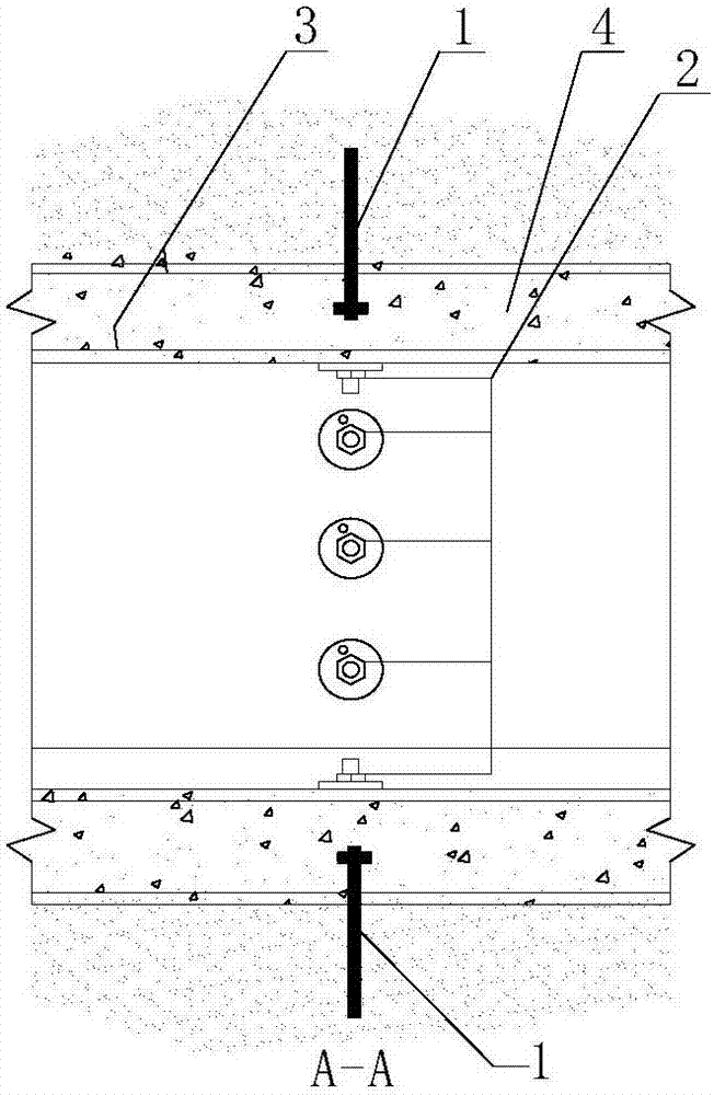
[0047] The bottom plate of the present invention is a flat inclined shaft wall structure, which is composed of anchor rod I1, anchor rod II2, steel skeleton 3, and concrete 4 (see Picture 1-1 , Figure 1-2 ).

[0048] Specific construction steps:

[0049] (1) After the wellbore of the inclined shaft in the aquifer is excavated, firstly, according to a certain axial and circumferential distance, drill holes in the surrounding rock mass and install the anchor rods I1 and II2; the outer end of the anchor rod I1 extends into the inside of the well wall 4 Instead of penetrating the shaft wall, the outer end of the anchor rod II2 penetrates the shaft wall concrete 4 just to reach its inner surface;

[0050] (2) Carry out the binding construction of the shaft wall steel skeleton 3, and firmly connect with the anchor rods I1 and II2 to form a three-dimensional steel skeleton, and con...

Embodiment 2

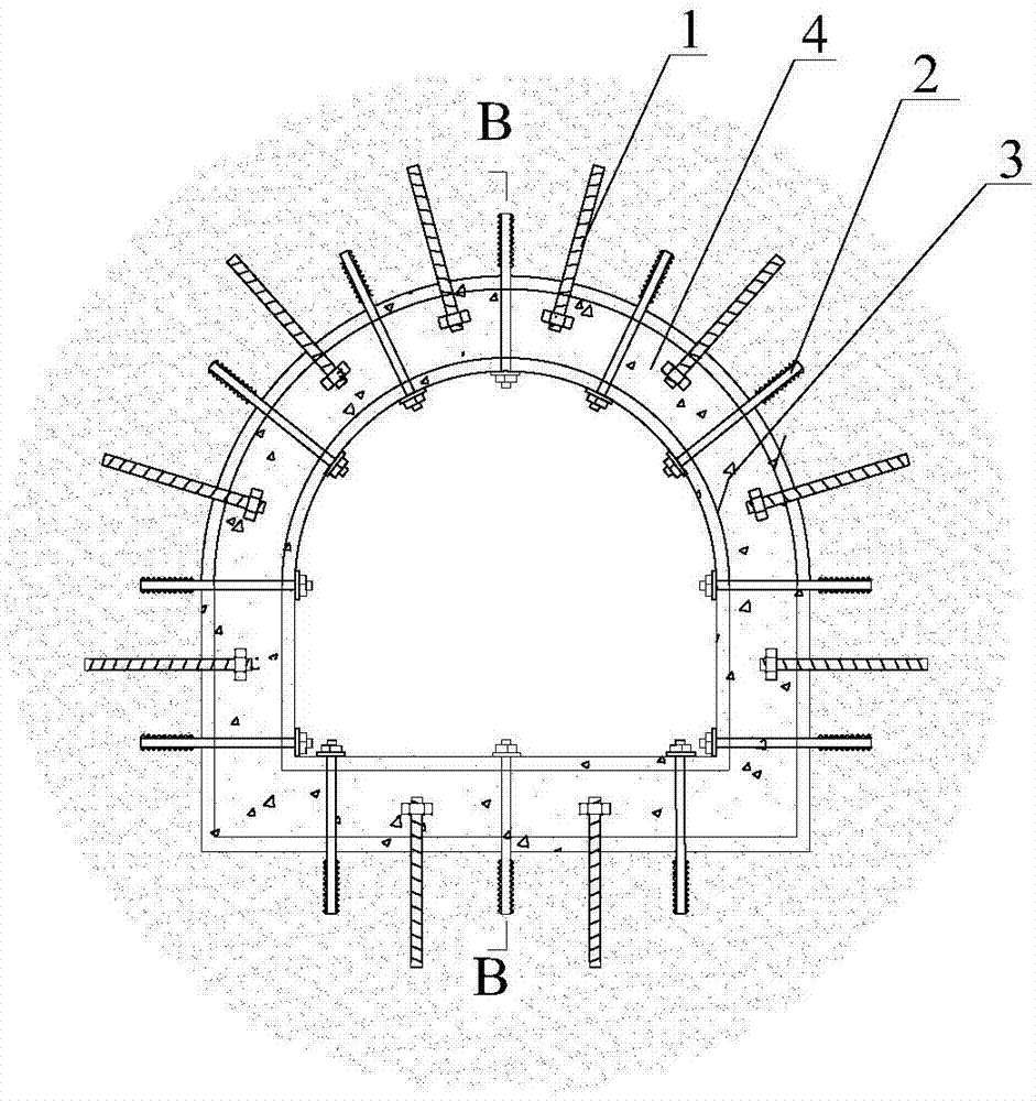
[0055] Embodiment 2: the bottom plate is a straight type inclined shaft wall structure;

[0056] The bottom plate of the present invention is a flat inclined shaft wall structure, which is composed of anchor rod I1, anchor rod II2, steel skeleton 3, and concrete 4 (see diagram 2-1 , Figure 2-2 ).

[0057] Others are the same as in Example 1.

Embodiment 3

[0058] Embodiment 3: shaft wall structure;

[0059] The shaft wall structure of the present invention is composed of anchor rod I1, anchor rod II2, steel skeleton 3, and concrete 4 (see Figure 3-1 , Figure 3-2 ).

[0060] Others are the same as in Example 1.


PUM


Abstract

A well wall structure and a construction method of a water-bearing rock formation, which belong to a well wall structure and a construction method. The well wall is the anchor rod I, anchor rod II, steel skeleton and concrete poured in the entire network frame to form the cylindrical well wall; firstly, the anchor rod I and anchor rod II are constructed on the surrounding rock mass Then bind the steel frame of the well wall, and connect the anchor rods I and II with the steel frame, and connect the pre-embedded grouting pipe; then set up the formwork and pour concrete; after the well wall is demolished and reaches a certain strength, screw the end nut , apply pre-tightening force to the anchor rod II; finally carry out grouting through the pre-embedded grouting pipe in the anchor rod II, the grout passes through the grout hole, and fills the pores at the interface between the well wall and the surrounding rock mass. After the grouting is completed, close the valve ;Advantages: The radial stiffness of the well wall is improved through the joint bearing of the well wall and the surrounding rock, avoiding the accumulation of high-pressure water on the outer surface of the well wall; under the same section size and material conditions, it has higher bearing capacity and greatly reduces the project cost. Improve security.

Description

technical field [0001] The invention relates to a well wall structure and a construction method, in particular to a well wall structure and a construction method of a water-bearing rock formation. Background technique [0002] The construction of underground projects such as vertical shafts and inclined shafts first faces the design problem of the shaft wall (supporting structure). For water-free or shallow low-pressure water-bearing rock formations, due to the small load, the design and construction of the shaft wall are less difficult, and the engineering safety can be guaranteed. [0003] However, the existing shaft and inclined shaft wall design codes do not pay attention to the value of hydraulic load in rock formations; and for deep water-bearing rock formations, water pressure is the most important load on the shaft wall. If the water pressure is not considered correctly, the design thickness of the well wall will be too thin, resulting in the well wall being unable ...

Claims


Application Information

Patent Timeline
Patent Type & Authority Patents(China)
IPC IPC(8): E21D5/11
Inventor 王衍森杨维好刘钦升文凯杨然
Owner CHINA UNIV OF MINING & TECH
Learn More