
Method and device for burning pulverized coal or pulverized coal to generate high-temperature high-oxygen torch ignition

A torch and coal crushing technology, which is applied in the directions of combustion ignition, combustion method, and ignition through the guide flare, can solve the problems of easy coking and large pre-combustion chamber volume in the coal-fired pre-combustion chamber.

Active Publication Date: 2017-11-24
XUZHOU KERONG ENVIRONMENTAL RESOURCES CO LTD
View PDF5 Cites 0 Cited by
  • Summary
  • Abstract
  • Description
  • Claims
  • Application Information

AI Technical Summary

Problems solved by technology

[0010] The purpose of the present invention is to provide a method and device for burning pulverized coal or pulverized coal to produce a high-temperature high-oxygen torch ignition, so as to solve the problems that the coal-fired pre-combustion chamber is easy to coke and the volume of the pre-combustion chamber is too large

Method used


Image

  • Method and device for burning pulverized coal or pulverized coal to generate high-temperature high-oxygen torch ignition
  • Method and device for burning pulverized coal or pulverized coal to generate high-temperature high-oxygen torch ignition

Examples


Embodiment 1

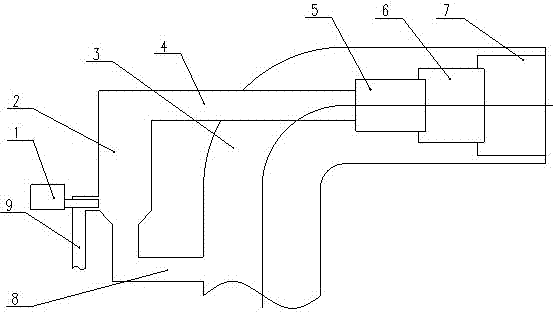
[0048] Embodiment 1: as figure 1 As shown, the device of the present invention includes: plasma generator I1, pre-combustion chamber I2, main burner 3, torch outlet I4, primary cylinder 5, secondary cylinder 6, third-stage cylinder 7, primary air duct 8 of pre-combustion chamber , Pre-combustion chamber secondary air duct 9.

[0049] The lower part of the pre-combustion chamber I2 is a constricted opening, through which the primary air duct 8 of the pre-combustion chamber is connected. The secondary air duct 9 of the combustion chamber and the secondary air duct 9 of the pre-combustion chamber are provided with an elbow before entering the pre-combustion chamber I2, and a hole is opened on the elbow, and the plasma generator I1 is inserted into the hole, and the upper part of the pre-combustion chamber I2 is connected to the torch Exit I4, the torch outlet I4 is smaller than the first-stage barrel 5, the right end of the torch outlet I4 is inserted into the first-stage barrel...

Embodiment 2

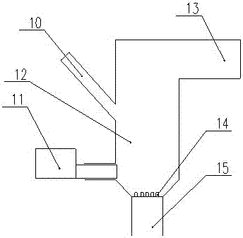
[0052] Embodiment 2: as figure 2 As shown, the pre-combustion chamber II12 is an adiabatic combustion chamber, which is generally arranged vertically. The lower part of the pre-combustion chamber II12 is connected to the wind cap 14, the lower part of the wind cap 14 is connected to the air inlet 15, the middle part of the pre-combustion chamber II12 is connected to the coal drop pipe 10, and the upper part of the pre-combustion chamber II12 is connected to the torch Exit II13.

[0053] Its working process: After the plasma generator Ⅱ11 heats the inner cavity of the pre-combustion chamber Ⅱ12, it puts crushed coal from the coal drop pipe 10 into the pre-combustion chamber Ⅱ12, and the smoke after ignition is ejected from the torch outlet Ⅱ13, and the combustion-supporting Air enters the pre-combustion chamber from the air inlet 15 through the air cap 14 to blow the pulverized coal into a fluidized state for fluidized combustion; by controlling the equivalent excess air coeff...


PUM


Abstract

The invention provides an ignition method and device through a high-temperature high oxygen torch generated by coal powder or crushed coal combustion and belongs to ignition method and devices of coal-burned boilers. The method includes the steps that coal powder or crushed coal is added to a vertical fluidized bed precombustion chamber, when the equivalent excessive air coefficient alpha' is larger than 1.3 and smaller than 2.6, the small amount of generated high-temperature high-oxygen torch which is burnt strongly is sent to a combustor, and the main fuel is ignited through a flame step-by-step amplification principle. The device comprises a plasma generator I, a precombustion chamber I, a main combustor, a torch outlet I, a first-level barrel, a second-level barrel, a third-level barrel, a primary air flue of a precombustor and a secondary air flue of a precombustor. By means of the ignition method and device, coal powder boiler oil-free ignition, circulating fluidized bed oil-free ignition, low-load stable combustion and low-nitrogen combustion can be achieved. The ignition method and device have the advantages that the precombustor is simple, reliable and free of coking after being operated for a long time; an external heat source, such as a plasma or oil gun can stop working after ignition is stable, and the precombustor is relied on for achieving stable combustion.

Description

technical field [0001] The invention relates to a method and a device for igniting a coal-fired boiler, in particular to a method and a device for igniting a high-temperature high-oxygen torch generated by burning pulverized coal or pulverized coal. Background technique [0002] Before the invention of plasma ignition and oil-less ignition technology, various pre-chamber ignition technologies were widely used in the ignition and stable combustion of pulverized coal furnaces. There are two main technical defects in the pre-chamber ignition technology: 1. Coking in the pre-chamber; 2. The volume of the pre-combustion chamber is too large, resulting in too large openings on the water wall of the boiler. Therefore, the pre-chamber ignition technology has been almost forgotten under the impact of plasma ignition and fuel-less ignition technology, but the low-load stable combustion technology accumulated based on pre-chamber technology has been widely retained. [0003] At presen...

Claims


Application Information

Patent Timeline
Patent Type & Authority Patents(China)
IPC IPC(8): F23Q9/00
Inventor 雍占锋张红月张举乐蒋允刚朱红胜
Owner XUZHOU KERONG ENVIRONMENTAL RESOURCES CO LTD
Learn More