Connecting joint non-orthogonal to cross column and construction method

A technology for connecting nodes and cross-columns, applied in the direction of buildings, building structures, etc., can solve the problems of overlapping welding seams, difficult to control the positioning accuracy of on-site construction, and difficult welding of non-orthogonal nodes of cross-columns, etc. Small angle and small space welding seam, the effect of welding seam quality is easy to ensure

Inactive Publication Date: 2016-01-06
ZHEJIANG JINGGONG STEEL BUILDING GRP
View PDF7 Cites 6 Cited by
  • Summary
  • Abstract
  • Description
  • Claims
  • Application Information

AI Technical Summary

Problems solved by technology

[0005] The purpose of the present invention is to provide a non-orthogonal connection node with the cross column and a construction method to solve the current problems such as the difficulty in welding the non-orthogonal node of the cross column, overlapping weld seams, and difficulty in controlling the positioning accuracy of on-site construction.

Method used


Image

  • Connecting joint non-orthogonal to cross column and construction method
  • Connecting joint non-orthogonal to cross column and construction method
  • Connecting joint non-orthogonal to cross column and construction method

Examples


Embodiment 1

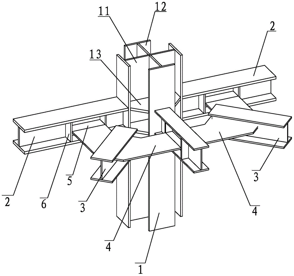
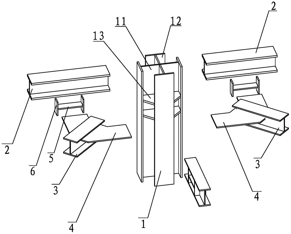
[0023] Such as Figure 1-3 As shown, a connection node that is non-orthogonal to the cross column, the related components include cross column 1, orthogonal steel beam corbel 2, non-orthogonal horizontal member 3, annular connecting plate 4, butt plate 5, stiffening plate 6.

[0024] Orthogonal steel beam corbel 2 and cross column 1 are conventionally welded, butt plate 5 is welded to the web of orthogonal steel beam corbel 2, both sides are reinforced with stiffening plates 6, and non-orthogonal horizontal members 3 are welded to annular connecting plate 4 , The annular connecting plate 4 is welded with the butt plate 5 at the construction site.

[0025] In this embodiment, the cross column 1 is usually a cross column inside a steel reinforced concrete column, which is generally manufactured in a factory.

[0026] Orthogonal steel beam corbel 2 is welded H-shaped steel, the length is generally the same as the height of the orthogonal steel beam web, and then rigidly connected to t...

Embodiment 2

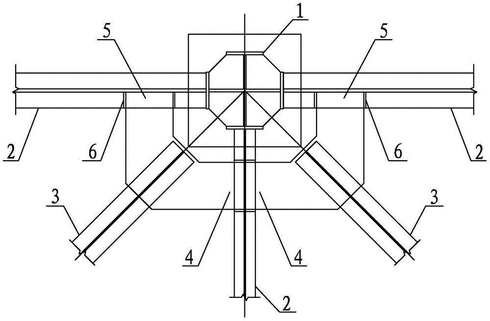
[0030] If the non-orthogonal horizontal member is a steel beam on the floor, the butt plate 5 can be turned into a vertical steel plate, connecting the upper and lower annular connecting plates, and other preferred embodiments of the present invention can be derived. See details Figure 4 .

[0031] The stiffening plates 6 are on both sides of the butting plate 5 to ensure the stability of the butting plate 5, strengthen the bearing capacity of the nodes, and share the force of the webs of the orthogonal steel beam corbels 2.

[0032] The annular connecting plate 4 is welded with the butt plate 5 on the steel beam to realize the connection with the corbel 2 of the orthogonal steel beam, which can avoid the complicated connection between the non-orthogonal member 3 and the cross column 1.

[0033] The ring-shaped connecting plate 4 avoids the outer skin of the steel-concrete column, which can prevent the non-orthogonal member 3 and the cross column 1 from being directly connected to th...


PUM


Abstract

The invention belongs to the field of steel structures, and particularly relates to a connecting joint non-orthogonal to a cross column and a construction method. The connecting joint non-orthogonal to the cross column comprises the cross column and steel brackets, wherein the steel brackets are welded to a peripheral surface of the cross column in an orthogonal mode; an annular connecting plate is fixedly welded between the adjacent steel brackets; and a horizontal component is fixedly welded on the annular connecting plate. Problems that connecting plates and stiffening ribs which correspond to a non-orthogonal component in a cross column are welded difficultly, weld joints are overlapped, rebars penetrate in steel plates, field construction positioning precision is difficult to control and the like are solved, after certain modification, various stress requirements can be met, a large amount of costs can be saved, and manufacturing and mounting efficiency is improved.

Description

Technical field [0001] The invention belongs to the field of steel structures, and specifically relates to a connection node that is not orthogonal to a cross column and a construction method. Background technique [0002] In multi- and high-rise civil buildings, when the structure height is high or the load is large, in order to reduce the size of the column section, the combined section of steel structure and concrete is usually used, that is, the steel concrete column, to give full play to the respective characteristics of the two materials. Advantage. The steel frame of the steel reinforced concrete column is mostly cross column. When the strengthening layer is to improve the horizontal rigidity of the floor, the steel structure support is often used. This support is generally non-orthogonal to the steel reinforced concrete column; in addition, the column and the internal cylinder Or when the internal columns are not on the same main axis, the horizontal members connecting t...

Claims


Application Information

Patent Timeline
Patent Type & Authority Applications(China)
IPC IPC(8): E04B1/24E04B1/58
Inventor 江涛王垒余波仝书敬杜兆宇俞奇效姚峰王柳
Owner ZHEJIANG JINGGONG STEEL BUILDING GRP
Why Eureka
Try Eureka