Edge coupling standing wave accelerating tube manufacture method and edge coupling standing wave accelerating tube

A manufacturing method and acceleration tube technology, which are applied in the directions of additive manufacturing, linear accelerators, additive processing, etc., can solve the problems of low yield in the field of acceleration tube production, restricting the stability of acceleration tube operation, complex forming technology, etc., so as to shorten the production time. Reduced cycle times, welding times, and improved cooling efficiency

Active Publication Date: 2017-11-24
SHANGHAI UNITED IMAGING HEALTHCARE
View PDF9 Cites 8 Cited by
  • Summary
  • Abstract
  • Description
  • Claims
  • Application Information

AI Technical Summary

Problems solved by technology

In addition, the coupling hole is also a through hole formed by first completing the processing of the main acceleration cavity and then hollowing out the side cavity in reverse. Therefore, the edge of the coupling hole produced by this processing method always has sharp corners. This type of structure The coupling hole will cause different degrees of microwave sparking problems in the later stage of the accelerating tube, which seriously restricts the operation stability of the accelerating tube
In addition, for some accelerated cavity structures with special requirements (such as reentrant side cavity structures, etc.), the current machining is difficult to complete, and it will be completed by means of deep drawing forming or casting forming, but this forming technology will be more Complex and low yield in the area of ​​accelerator tube production

Method used


Image

  • Edge coupling standing wave accelerating tube manufacture method and edge coupling standing wave accelerating tube
  • Edge coupling standing wave accelerating tube manufacture method and edge coupling standing wave accelerating tube
  • Edge coupling standing wave accelerating tube manufacture method and edge coupling standing wave accelerating tube

Examples


Embodiment Construction

[0046] The specific embodiments of the present invention will be described in detail below in conjunction with the accompanying drawings, but the present invention can be implemented in many different ways defined and covered by the claims.

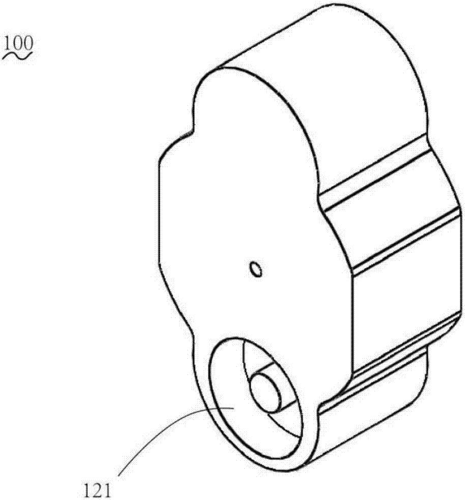
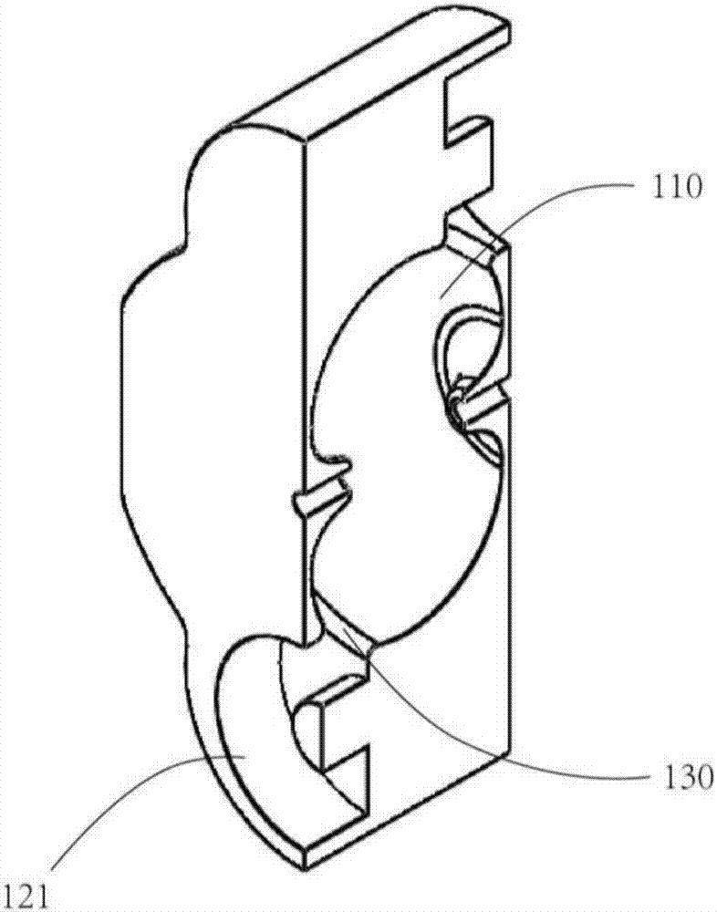
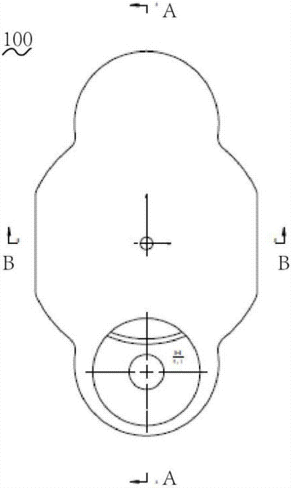
[0047] Such as Figure 1-Figure 5 As shown, the single-period acceleration cavity unit 100 of the side-coupled standing wave acceleration tube in the present invention is integrally formed and made by 3D printing technology, and has a main acceleration cavity 110 and two half-side coupling cavities connected with the main acceleration cavity 110 121. The two half coupling cavities 121 are respectively arranged on both sides of the main acceleration chamber 110 along the particle acceleration direction, and are arranged symmetrically with respect to the center of the main acceleration chamber 110 . Such as Figure 6 and Figure 7As shown, a plurality of single-cycle accelerating cavity units 100 are connected in sequence, the main accel...


PUM


Abstract

The invention provides an edge coupling standing wave accelerating tube manufacture method, and relates to the field of medical electron linear accelerators. The invention provides an edge coupling standing wave accelerating tube manufacture method which has the advantages of simple manufacture process and high operating stability of a manufactured accelerating tube, and an edge coupling standing wave accelerating tube. The edge coupling standing wave accelerating tube has a main accelerating chamber without weld joints, has the chamber body with low ignition risk, and is not limited by machining molding conditions. The edge coupling standing wave accelerating tube manufacture method provided by the invention has the advantages that an integrally formed single-cycle accelerating chamber body unit is manufactured through a 3D printing technology; a first time of heating is carried out on the printed single-cycle accelerating chamber body unit; the single-cycle accelerating chamber body unit is mechanically ground and polished through a grinding material; the mechanically ground and polished single-cycle accelerating chamber body unit is cleaned; and the cleaned single-cycle accelerating chamber body unit is assembled to form the edge coupling standing wave accelerating tube.

Description

technical field [0001] The invention relates to the field of medical electron linear accelerators, in particular to a manufacturing method of a side-coupling standing wave accelerating tube and a side-coupling standing wave accelerating tube. Background technique [0002] The accelerator tube is a key component of a medical electron linear accelerator, and its function is to generate high-energy rays for clinical cancer treatment and imaging. At present, many manufacturers of medical electron accelerator tubes are using the side-coupled standing wave accelerator tube structure. The side-coupled cavity is set on both sides of the acceleration path. The electrons provided by the electron gun obtain energy under the action of the microwave field in the main acceleration cavity, and pass The beam hole in the center of the accelerating cavity reaches the outlet of the accelerating tube, while the microwave power in it is coupled and transmitted through the coupling hole between t...

Claims


Application Information

Patent Timeline
IPC IPC(8): H05H7/22H05H9/04B22F3/105B22F3/24B33Y10/00
CPCH05H7/22H05H9/04B22F3/24B33Y10/00H05H2007/225B22F2003/248B22F2003/247B22F2003/241B22F10/00B22F10/32B22F10/66B22F10/64B22F10/68B22F10/28Y02P10/25
Inventor 贺守波
Owner SHANGHAI UNITED IMAGING HEALTHCARE
Why Eureka
Try Eureka