Drill rod clamping device

A drill pipe clamping and clamping device technology, applied to drill pipes, drill pipes, drilling equipment, etc., can solve the problems of high production cost, troublesome replacement, clamping failure, etc., and achieve long service life, low manufacturing cost, Reliable clamping effect

Active Publication Date: 2016-01-06
CHTC JOVE HEAVY IND
View PDF7 Cites 13 Cited by
  • Summary
  • Abstract
  • Description
  • Claims
  • Application Information

AI Technical Summary

Problems solved by technology

Although this structure solves the technical problems of unreliable clamping and positioning, slipping, and collapse of the drill pipe due to wear and scratches of the drill pipe to a certain extent, resulting in structural instability, but when the structure is used for a long time, the rolling groove accommodates During the construction process, due to the long-term continuous extrusion of the moving parts or rolling parts, the moving parts or rolling parts will be squeezed and deformed, or even cracked and damaged, which will eventually lead to clamping failure. Therefore, it is necessary to Continuous replacement of moving parts or rolling parts increases the manufacturing cost and makes replacement troublesome due to complex structure
[0005] In order to further solve technical problems such as high production cost, complex structure, and troublesome replacement, further research and design are needed to adapt to industrial economical production

Method used


Image

  • Drill rod clamping device
  • Drill rod clamping device
  • Drill rod clamping device

Examples


Embodiment

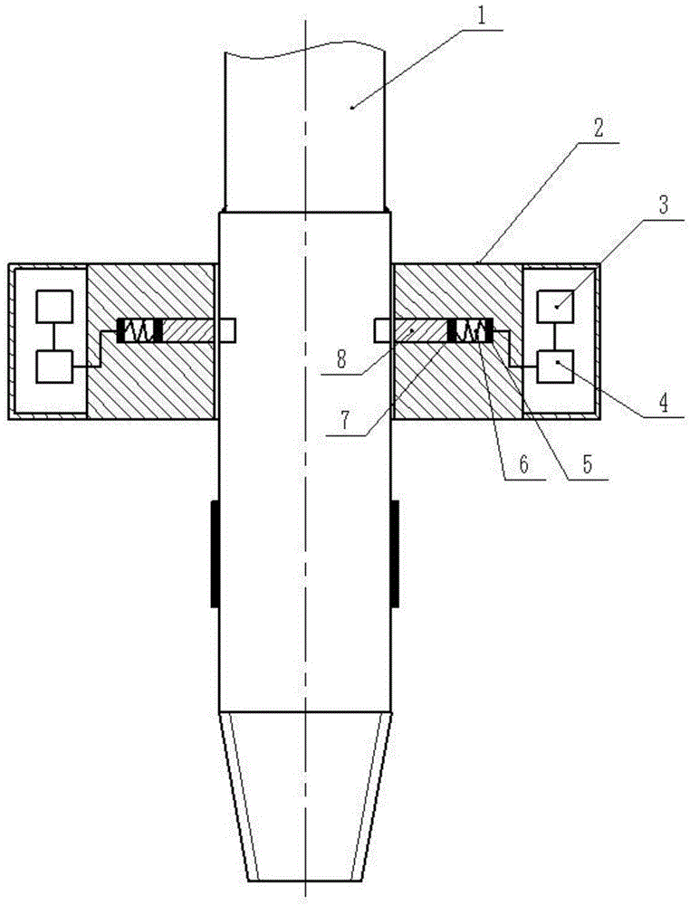
[0030] Such as Figure 5 As shown, a drill pipe clamping device provided by the present invention includes a drill pipe 1, the drill pipe 1 is composed of a drill pipe joint and a steel pipe 12, the drill pipe joint is welded with the steel pipe 12, and the drill pipe joint Conical thread section 16, wear-resistant section 15, and non-wear-resistant section 13. The circumference of the non-wear-resistant section 13 of the drill pipe joint is provided with an outer arc groove 14, and the non-wear-resistant section 13 of the drill pipe joint The maximum depth of the outer arc grooves 14 on the circumference of the section 13 is smaller than the wall thickness of the drill pipe joint. Evenly distributed along the circumference.

[0031] The function of the wear-resistant section 15 of the drill pipe joint: the drill pipe joint wears quickly because the drill pipe joint is subjected to erosion and wear while undergoing severe wear. In order to improve the wear resistance of the ...


PUM


Abstract

The invention discloses a drill rod clamping device. The drill rod clamping device comprises a drill rod and a clamping device body. The drill rod is composed of a drill rod connector and a steel pipe. The drill rod connector is welded to the steel pipe. The drill rod connector is composed of a taper thread section, an anti-abrasion section and a non-anti-abrasion section. An outer arc groove is formed in the circumference of the non-anti-abrasion section of the drill rod connector. The clamping device body comprises a clamping box. The clamping box is composed of a cavity part and a solid core part. The cavity part is provided with an infrared receiving circuit and a control circuit. The infrared receiving circuit is electrically connected with the control circuit. The solid core part is provided with a groove. An electromagnet is fixed to the bottom of the groove and sequentially and fixedly connected with a magnet and a sliding block through a spring. The magnet is fixed to the sliding block. The sliding block can move leftwards and rightwards along the groove. The drill rod clamping device is simple in structure, convenient to operate, reliable in clamping, long in service life, low in manufacturing cost, free of abrasion and scratches to the drill rod and free of slipping.

Description

technical field [0001] The invention relates to the technical field of engineering drilling equipment, in particular to a drill pipe clamping device for a core drilling machine. Background technique [0002] The core drilling rig has the characteristics of modular design, easy disassembly and assembly, high drilling efficiency, convenient transportation, low cost, and environmental protection. It can drill into strata with a depth of less than 350m, and can be widely used in core drilling work with extremely complex ground conditions. [0003] There are many types of core drilling rigs in my country, but there are many problems in the clamping and positioning of the drill rods of the existing core drilling rigs. The clamping and positioning of the drill rods are generally in the form of clamping by butterfly springs and automatic centering of slips. During use, because the drill pipe is clamped by slips, the drill pipe will be worn and scratched, which will lead to a series ...

Claims


Application Information

Patent Timeline
IPC IPC(8): E21B19/10E21B17/02E21B17/10
Inventor 黄建华王睿
Owner CHTC JOVE HEAVY IND
Why Eureka
Try Eureka