
Closed-loop detection method of atomic gyroscope on basis of photoelastic modulation

An atomic gyroscope and closed-loop detection technology, which is applied in the direction of measuring devices, instruments, steering sensing equipment, etc., can solve the problems of decreased modulation amplitude, reduced detection accuracy, and difficulty in stabilizing the scale factor

Active Publication Date: 2016-01-06
BEIJING AUTOMATION CONTROL EQUIP INST
View PDF5 Cites 32 Cited by
  • Summary
  • Abstract
  • Description
  • Claims
  • Application Information

AI Technical Summary

Problems solved by technology

This results in a drop in the Faraday modulation amplitude, reducing the signal-to-noise ratio of the detection system
[0005] The photoelastic modulation method is similar to the Faraday modulation method. The photoelastic modulation is used instead of the Faraday modulation. The system output still includes scale factors such as light intensity and modulation amplitude. The scale factor is difficult to stabilize and reduces the detection accuracy.
However, there is no atomic gyroscope detection method that can isolate and detect interferences such as laser light intensity fluctuations, Faraday modulation amplitude fluctuations, and photoelastic modulation amplitude fluctuations, so as to achieve high-precision detection of atomic gyroscopes and improve the accuracy of atomic gyroscopes.

Method used


Image

  • Closed-loop detection method of atomic gyroscope on basis of photoelastic modulation
  • Closed-loop detection method of atomic gyroscope on basis of photoelastic modulation
  • Closed-loop detection method of atomic gyroscope on basis of photoelastic modulation

Examples


Embodiment Construction

[0028] The technical solutions of the present invention will be further described in detail below through specific examples.

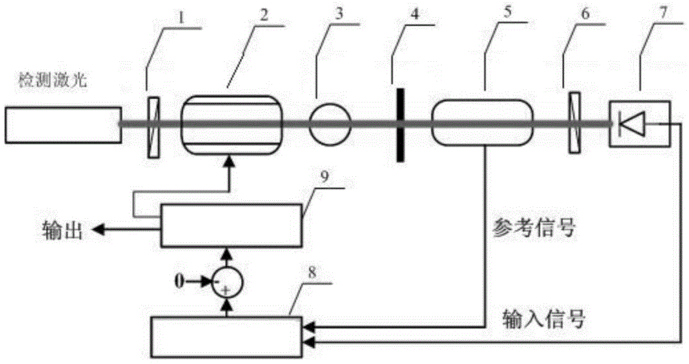
[0029] as attached figure 1 Shown, a kind of atomic gyroscope closed-loop detection method based on photoelastic modulation of the present invention comprises the following steps:

[0030] (1) A beam of detection laser passes through the polarizer, Faraday modulator, atomic gas cell, 1 / 4 wave plate, photoelastic modulator, analyzer and photodetector in sequence, and makes the fast axis of the 1 / 4 wave plate The same direction as the optical axis of the polarizer, the fast axis of the photoelastic modulator forms an angle of 45 degrees with the optical axis of the polarizer, and the angle of the analyzer and the optical axis of the polarizer forms a 90 degree angle, so that the 1 / 4 wave plate, photoelastic The Jones matrices of the modulator, analyzer, atomic gas cell, and Faraday modulator satisfy the following relations respectively:

[0031] ...


PUM


Abstract

The invention provides a closed-loop detection method of an atomic gyroscope on the basis of photoelastic modulation. The closed-loop detection method comprises the following steps: a Faraday actuator is placed in front of a 1 / 4 wave plate and a photoelastic modulator; detection laser passes through a polarizer, a Faraday modulator, an alkali-metal gas chamber, the 1 / 4 wave plate, the photoelastic modulator and an analyzer in sequence, a fast axis of the 1 / 4 wave plate and an optical axis of the polarizer are in the same direction, a fast axis of the photoelastic modulator and the optical axis of the polarizer form a 45-degree angle, and the analyzer and the optical axis of the polarizer form a 90-degree angle; a deflection angle of the closed-loop Faraday actuator is controlled by a PID (Proportion Integration Differentiation) controller, the output of a lock-phase amplifier is kept to be zero, and at the same time, the rotating angle to be detected is read out by an output angle of the closed-loop Faraday actuator. The closed-loop detection method provided by the invention has the advantages that the rotating angle to be detected is only related to the rotating angle of the closed-loop Faraday actuator and is not related to the light intensity and the photoelastic modulation amplitude, so that the influence of parameter fluctuation on a detection system is isolated on the principle, a scale factor of the closed-loop photoelastic modulation detection is easily stabilized, and the detection accuracy of the atomic gyroscope is improved.

Description

technical field [0001] The invention belongs to the technical field of atomic gyroscope detection methods, in particular to a photoelastic modulation-based atomic gyroscope closed-loop detection method suitable for SERF atomic spin gyroscopes and nuclear magnetic resonance gyroscopes. Background technique [0002] The detection of atomic spin precession can finally be mapped to the detection of the rotation angle of the polarization plane of the linear polarization detection laser. At present, there are mainly three detection methods for the linear polarization rotation angle of SERF atomic spin gyroscopes and nuclear magnetic resonance gyroscopes: differential Faraday modulation method, photoelastic modulation method and differential polarization method. [0003] The differential polarization method has the advantages of simple structure and easy implementation. However, due to the lack of modulation, when the atomic spin precession angle to be measured is a low-frequency ...

Claims


Application Information

Patent Timeline
Patent Type & Authority Applications(China)
IPC IPC(8): G01C25/00G01C19/60
CPCG01C19/60G01C25/005
Inventor 郑辛万双爱秦杰汪世林孙晓光
Owner BEIJING AUTOMATION CONTROL EQUIP INST
Learn More